Systems and methods for a spdt switch or spmt switch with transformer

a technology of spdt switch and transformer, which is applied in the field of systems and methods for spdt switch or spmt switch with transformer, can solve the problems of preventing the achievement of large isolation, high insertion loss cannot be avoided, and the technology is one of the most expensive technologies. achieve the effect of low insertion loss

Active Publication Date: 2011-03-24
GEORGIA TECH RES CORP +1
View PDF8 Cites 38 Cited by
  • Summary
  • Abstract
  • Description
  • Claims
  • Application Information

AI Technical Summary

Benefits of technology

[0004]Systems and methods may provide a SPDT or SPMT switch with a transformer that may include multiple switches and a transformer. The transmitter block (TX) output network may be provided by the transformer. Two switches may be connected to the secondary winding of the transformer. A first of the two switches, which may operate as a TX switch, may be located between the secondary winding and ground. The voltage swing at the TX switch may be very small at the ON state because of very low impedance. Therefore, the TX switch can be implemented with a transistor which has a low breakdown voltage even though the SPDT or SPMT switch handles high power. Low insertion loss may also be achieved without the need of a cascaded switch structure.

Problems solved by technology

The size of transistor for a switch should be large to achieve small insertion loss with a multiple parallel configuration, but a large transistor brings parallel large parasitic capacitance and prevents the achievement of large isolation.
However, the technology is one of the most expensive technologies.
In that case, series switches are cascaded to overcome high voltage swing from the high power but high insertion loss cannot be avoided.

Method used


Image

  • Systems and methods for a spdt switch or spmt switch with transformer
  • Systems and methods for a spdt switch or spmt switch with transformer
  • Systems and methods for a spdt switch or spmt switch with transformer

Examples


Embodiment Construction

[0021]Embodiments of the invention now will be described more fully hereinafter with reference to the accompanying drawings, in which some, but not all embodiments of the invention are shown. Indeed, these inventions may be embodied in many different forms and should not be construed as limited to the embodiments set forth herein; rather, these embodiments are provided so that this disclosure will satisfy applicable legal requirements. Like numbers refer to like elements throughout.

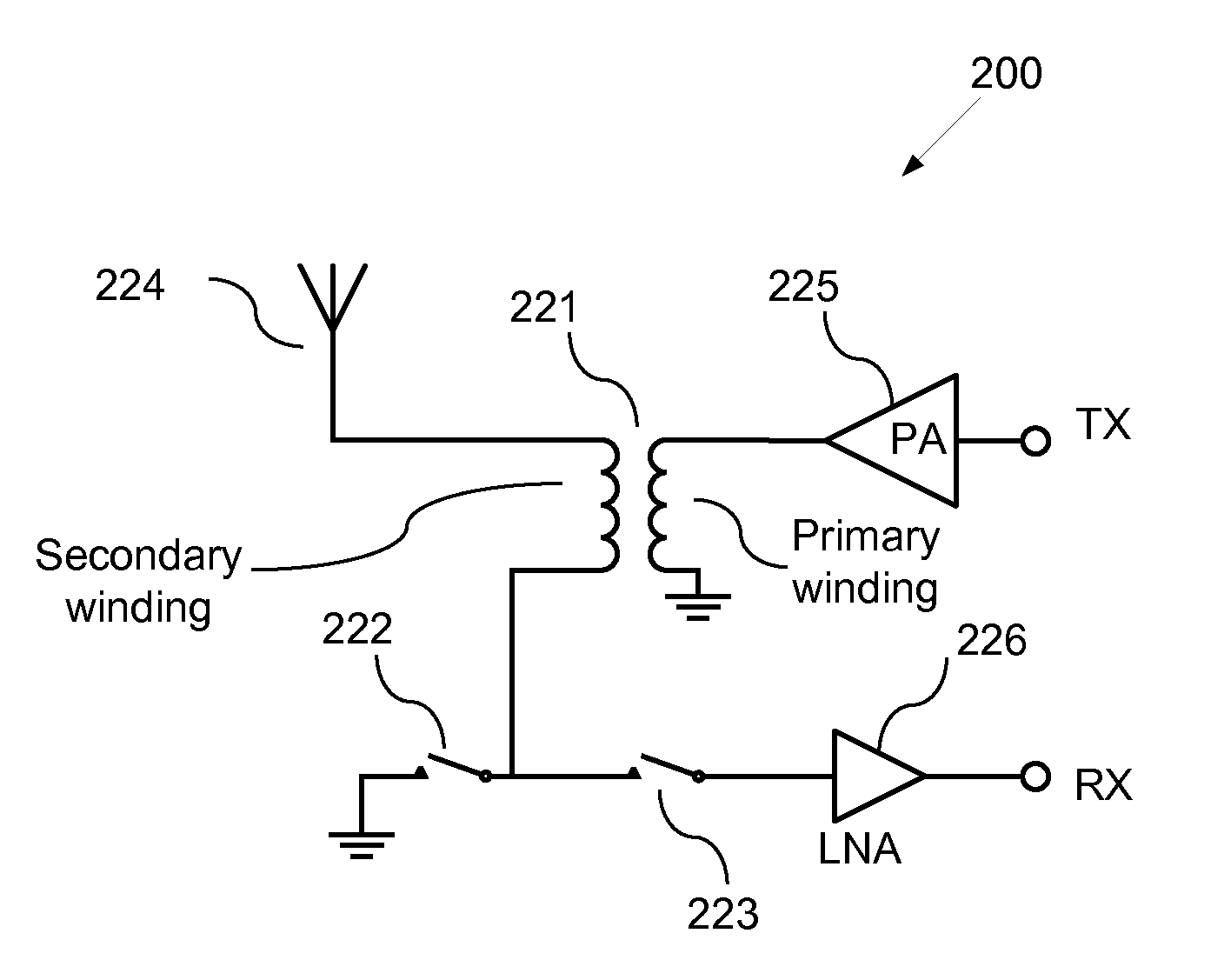
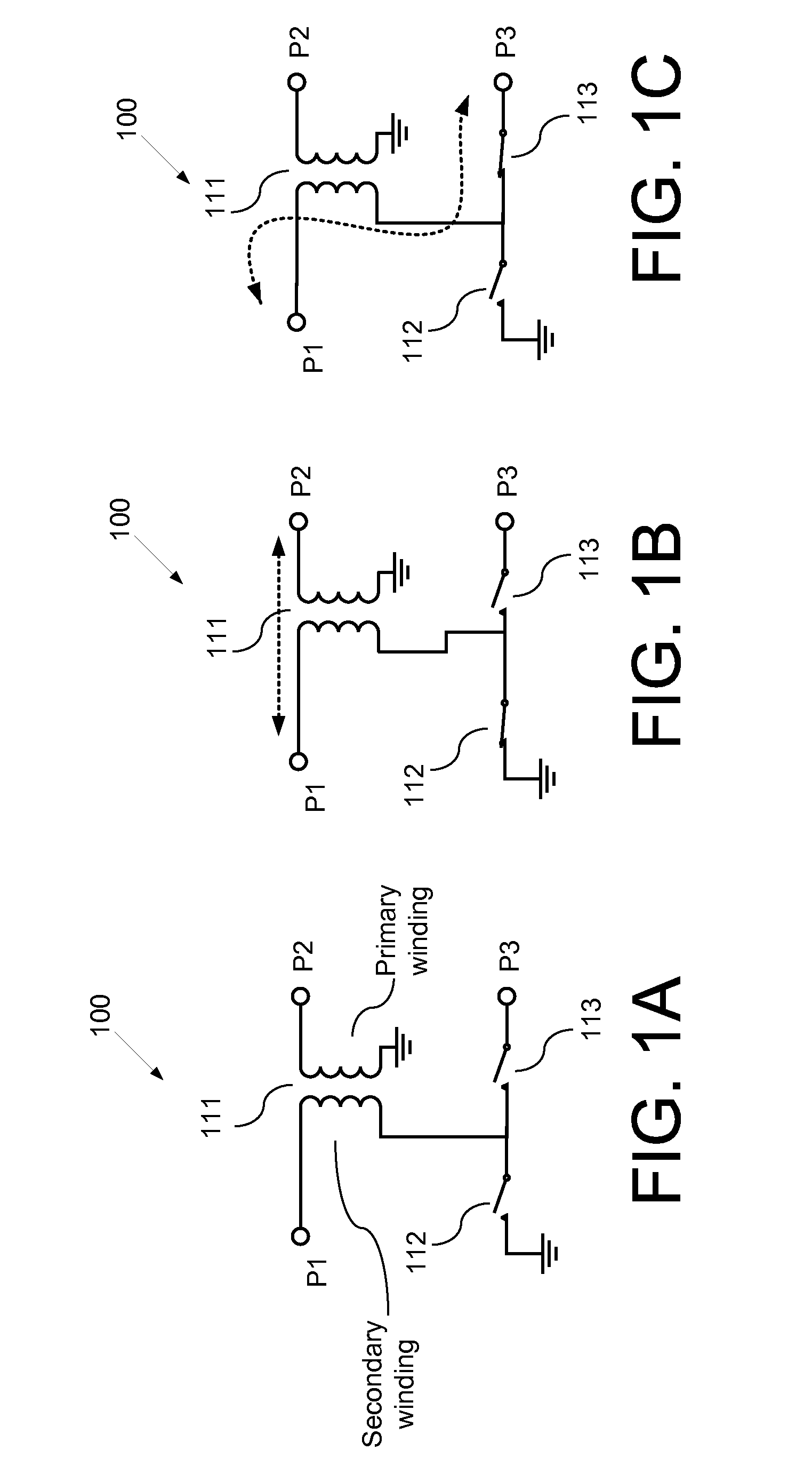
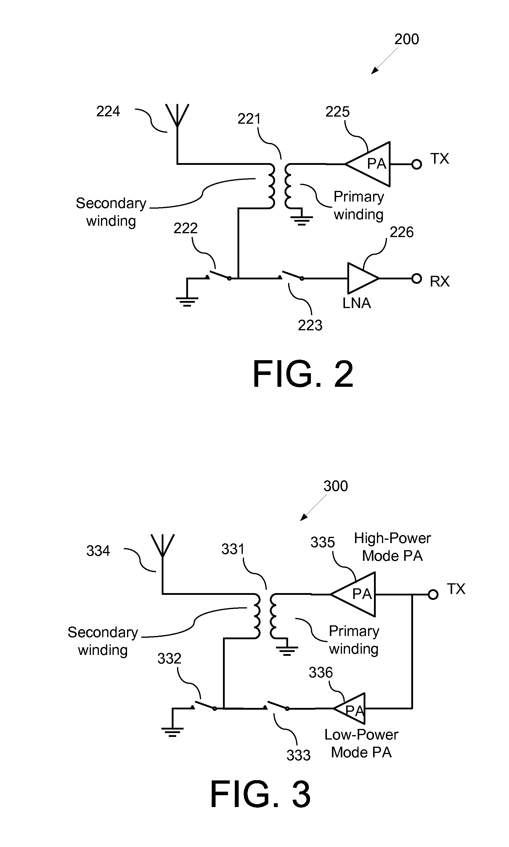
[0022]Example embodiments of the invention may provide for a SPDT switch or SPMT switch with a transformer, which may be comprised of multiple switches and one or more transformers. The one or more transformers may be used for implementing a transmit block (TX) output network, according to an example embodiment of the invention. Two switches may be connected to the secondary winding of the transformer. The TX switch may be located between the secondary winding and ground. The voltage swing at the TX switc...


PUM


Abstract

A SPDT or SPMT switch may include a transformer having a primary winding and a secondary winding, where a first end of the secondary winding is connected to a single pole port, where a first end of the primary winding is connected to a first throw port; a first switch having a first end and a second end, where the first end is connected to ground; and a second switch, where a second end of the secondary winding is connected to both a second end of the first switch and a first end of the second switch, where a second end of the second switch is connected to a second throw port, where the first switch controls a first communication path between the single pole port and the first throw port, and where the second switch controls a second communication path between the second throw port and the single pole port.

Description

FIELD OF INVENTION[0001]The invention relates generally to a single pole double throw (SPDT) switch or a single pole multi-throw (SPMT) switch, and more particularly, to systems and methods for a SPDT switch or SPMT switch with a transformer.BACKGROUND OF THE INVENTION[0002]Single pole double throw (SPDT) switches for mobile handsets are typically located between an antenna and a radio front-end. Generally, one switch is located between a transmitter block (TX) output and an antenna; the other is located between a receiver block (RX) input and an antenna. Both switches never close simultaneously to prevent a direct path from TX to RX. The switches are required to have small insertion loss for minimum power loss in transmit mode, and noise figure and large isolation for minimum leakage in receive mode. There exist trade-offs between small insertion loss and large isolation. The size of transistor for a switch should be large to achieve small insertion loss with a multiple parallel co...

Claims


Application Information

Patent Timeline
Patent Type & Authority Applications(United States)
IPC IPC(8): H03K17/00
CPCH03K17/693
Inventor LEE, DONG HOAHN, MINSIKAN, KYU HWANWOO, WANGMYONGLEE, CHANG-HOLASKAR, JOY
Owner GEORGIA TECH RES CORP
Why Eureka
Try Eureka