Method and circuit arrangement for cycle-by-cycle control of a LED current flowing through a LED circuit arrangement, and associated circuit composition and lighting system

Active Publication Date: 2011-03-24
NXP BV
View PDF5 Cites 51 Cited by
  • Summary
  • Abstract
  • Description
  • Claims
  • Application Information

AI Technical Summary

Benefits of technology

The present invention aims to improve the accuracy of the switch mode converter. In particular, the present invention aim

Problems solved by technology

However, when increasing the switching frequency in a switch-mode converter like the hysteretic converter, the controlling of the increase and decrease of the current in response to a crossover of the converter current sensing voltage of the upper of lower trip voltage will not be perfect.
The change of increasing to decreasing, or vice versa, may not be immediate, e.g. due to circuit delays, and may be associated with overshoots above the peak amperage and undershoots

Method used


Image

  • Method and circuit arrangement for cycle-by-cycle control of a LED current flowing through a LED circuit arrangement, and associated circuit composition and lighting system
  • Method and circuit arrangement for cycle-by-cycle control of a LED current flowing through a LED circuit arrangement, and associated circuit composition and lighting system
  • Method and circuit arrangement for cycle-by-cycle control of a LED current flowing through a LED circuit arrangement, and associated circuit composition and lighting system

Examples


Example

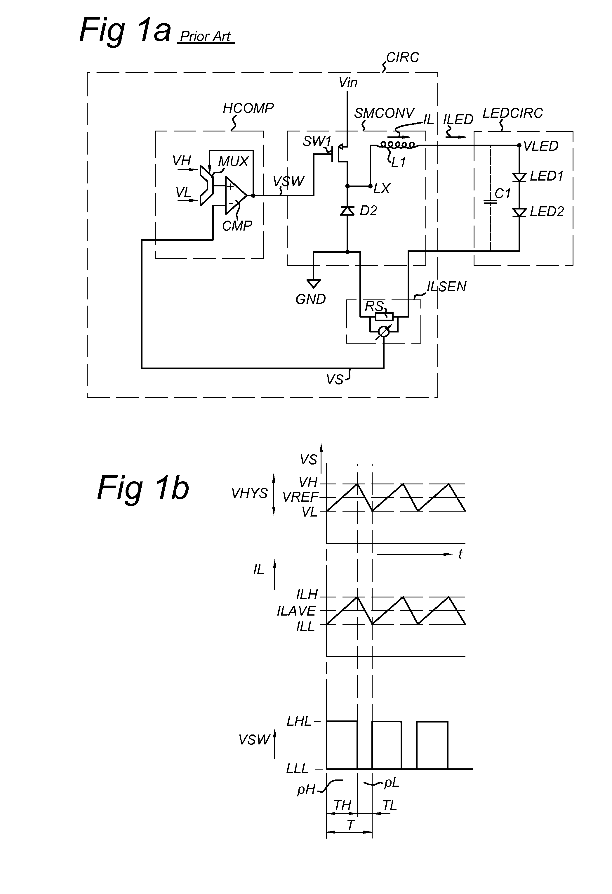
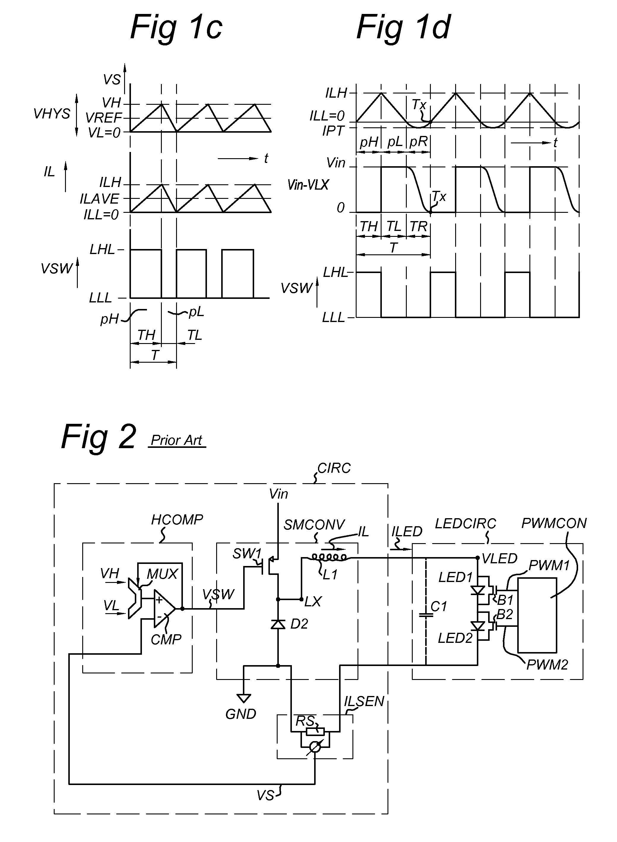
FIG. 1a schematically shows a circuit arrangement CIRC according to the prior art, supplying a current to a fixed LED arrangement LEDCIRC. FIG. 1b shows electrical signals related to the circuit arrangement CIRC shown in FIG. 1a when operated as a hysteretic Buck-converter; FIG. 1c shows electrical signals related to the circuit arrangement CIRC shown in FIG. 1a when operated as a normal Buck-converter; FIG. 1d shows electrical signals related to the circuit arrangement CIRC shown in FIG. 1a when operated as a boundary-conduction mode Buck-converter.

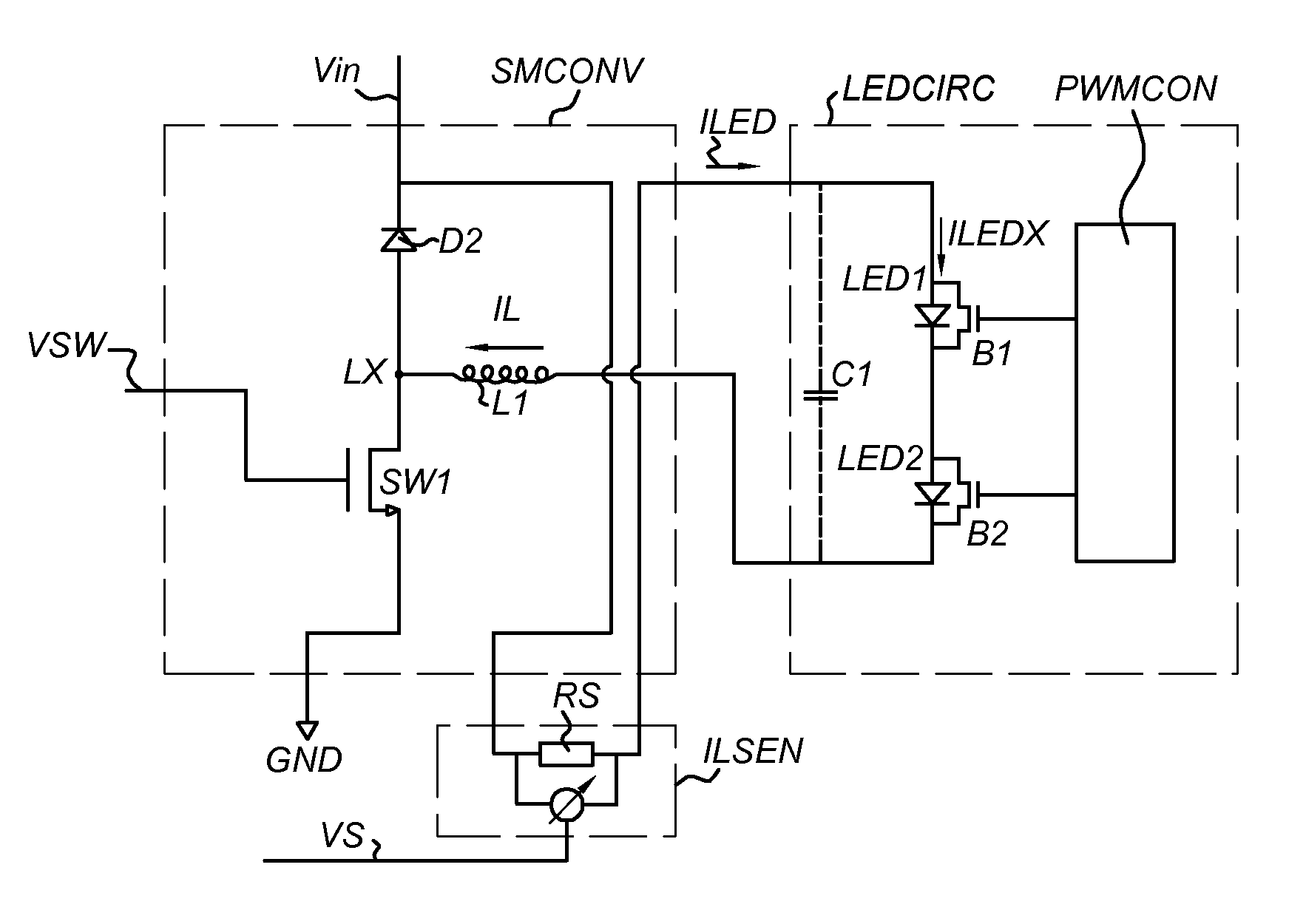
The circuit arrangement CIRC is arranged for regulating a mean current level of a LED current ILED flowing through a LED arrangement LEDCIRC. In the example shown, the LED arrangement LEDCIRC is a series arrangement of a first light emitting diode LED1 and a second light emitting diode LED2. The LED arrangement may further comprise an optional capacitive filter C1 to smoothen the current through the LEDs LED1, LED2. The example shown use...


PUM


Abstract

The invention provides a method for cycle-by-cycle control of a LED current (ILED) flowing through a LED circuit arrangement (LEDCIRC) at a mean LED current level. The method comprises a) establishing a converter current (IL), b) establishing an oscillation of the converter current (IL) between substantially a valley current level and substantially a peak current level, c) feeding the LED circuit arrangement (LEDCIRC) with the converter current (IL) as the LED current during a part of an oscillation cycle of the oscillation of the converter current, d) determining a current level correction for compensating a current level error between an integral over an oscillation cycle of the LED current and a reference, the reference being representative of the mean LED current level, and e) adjusting at least one of the valley current level and the peak current level with the current level correction for use in a successive cycle of the oscillation of the converter current. The invention also provides a circuit arrangement operable for using the method, a LED driver IC using the circuit arrangement, a circuit composition with at least one LED and the circuit arrangement, and a lighting system with the circuit composition.

Description

FIELD OF THE INVENTIONThe invention relates to a method for cycle-by-cycle control of a LED current flowing through a LED circuit arrangement at a mean LED current level. The invention further relates to a circuit arrangement for cycle-by-cycle control of a LED current flowing through a LED circuit arrangement at a mean LED current level. The invention further relates to a LED driver IC. The invention further relates to a circuit composition and to a LED lighting system.BACKGROUND OF THE INVENTIONThe light output of a light emitting diode is generally controlled by regulating a current level of a LED current through the LED. The LED current may be further modulated with, e.g. a pulse width modulation (PWM) scheme. In such a PWM-scheme, the LED receives the LED current in a periodic sequences of pulses of a certain width, while the width of the pulses is modulated from a first pulse width to a second pulse width when the effective light output is to be changed from a first light outp...

Claims


Application Information

Patent Timeline
IPC IPC(8): H05B41/36H05B44/00
CPCH05B33/083H05B33/0815H05B45/48H05B45/3725H05B45/375H05B45/38
Inventor HOOGZAAD, GIANLANGESLAG, WILHELMUS H. M.PANSIER, FRANSZHANG, CHENG
Owner NXP BV
Why Eureka
Try Eureka