Multi-Band antenna System for Satellite Communications

Active Publication Date: 2011-03-24
KVH IND INC
View PDF17 Cites 281 Cited by
  • Summary
  • Abstract
  • Description
  • Claims
  • Application Information

AI Technical Summary

Benefits of technology

[0014]As will be apparent from the description provided herein, the systems of the present invention are not only capable of simultaneously

Problems solved by technology

In cases where the satellites are very close to each other, it creates a challenge for reflector antenna systems often resulting in compromised performance and/or increased cost and complexity.
However, the patent fails to disclose the antenna device on a moving platform and also fails to disclose any time of movement of the reflector including its components to track separate frequency signals.
However, in this

Method used


Image

  • Multi-Band antenna System for Satellite Communications
  • Multi-Band antenna System for Satellite Communications
  • Multi-Band antenna System for Satellite Communications

Examples


Embodiment Construction

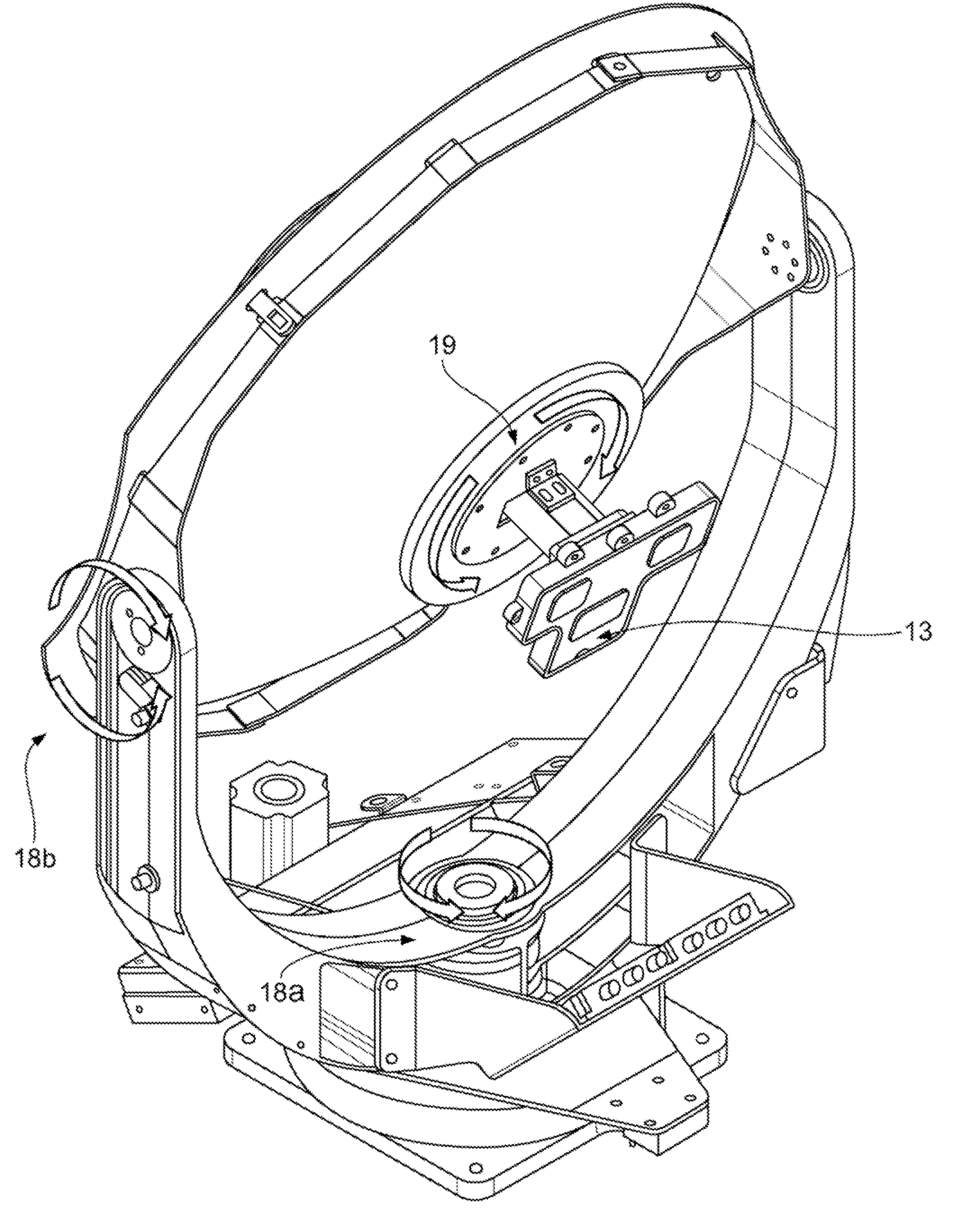
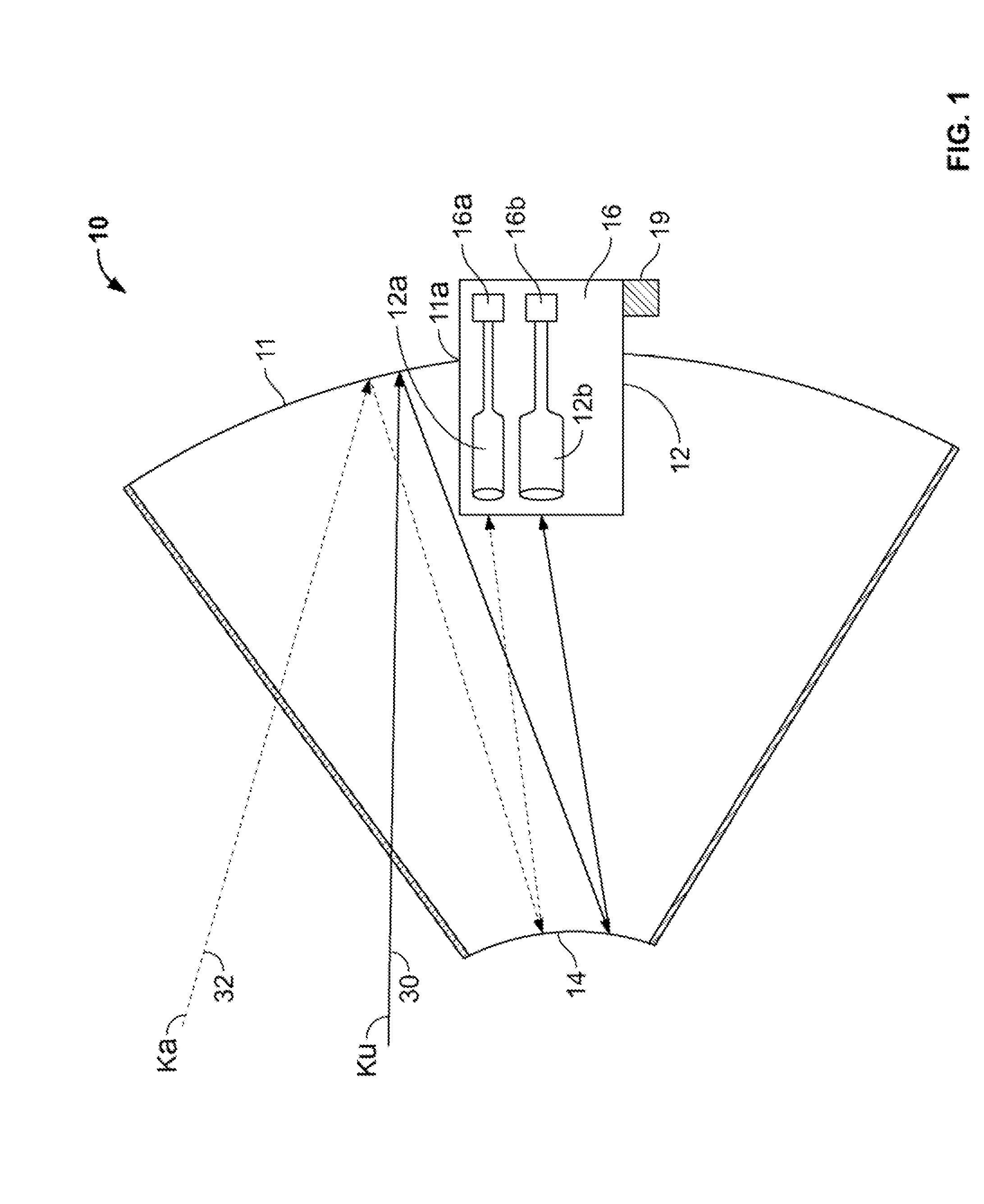
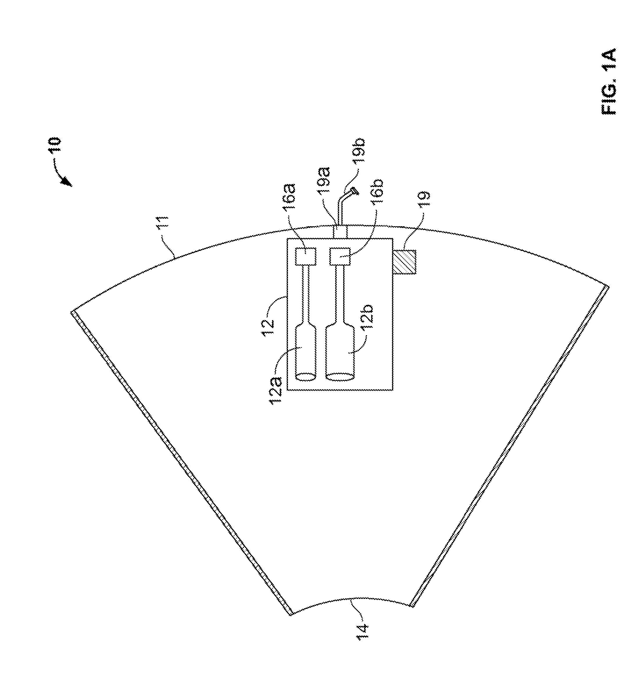
[0023]FIG. 1 illustrates a schematic view of a preferred embodiment of the satellite-antenna system 10 installed on a roof of a moving platform (not shown) configured to receive at least three separate RF signals in accordance with an embodiment of the present invention. The antenna system 10 is preferably an axially symmetrical reflector system. The system 10 includes a primary reflector 11, having at least one opening 11a. The reflector shown in the present embodiment is a parabola-shaped reflector and is preferably made of metals such as aluminum or steel, however the other construction materials may be used, such as carbon fiber. The system 10 further includes a feed horn assembly 12 having at least two feed tubes / horns 12a, and 12b extending from the front to the rear of the primary reflector 11 via the opening 11a. As an example shown in FIG. 1, the feed horn 12a is configured to receive Ka signal 30 and the feed horn 12b is configured to receive a Ku signal 32. Feed horns 12a...


PUM


Abstract

The present invention provides an improved antenna system on moving platform that is in communication with multiple satellites for simultaneous reception of RF energy at multiple frequencies. The antenna is implemented as a multi-beam, multi-band antenna having a main reflector with multiple feed horns and a sub-reflector to reflect Ku and Ka frequency band signals directed by a focal region of the main reflector.

Description

CROSS REFERENCES[0001]This patent application claims the benefit of U.S. Provisional Application Ser. No. 61 / 244,260 filed Sep. 21, 2009, the contents of which are incorporated by reference herein.FIELD OF THE INVENTION[0002]The present invention is generally related to the field of satellite communications and antenna systems, and is more specifically directed to multi-band antenna systems that allow simultaneous reception of RF energy from multiple satellites positioned in several orbital slots broadcasting at multiple frequencies.BACKGROUND OF THE INVENTION[0003]An increasing number of applications are requiring systems that employ a single antenna designed to receive RF energy from multiple satellites positioned in several orbital slots broadcasting at multiple frequencies. In cases where the satellites are very close to each other, it creates a challenge for reflector antenna systems often resulting in compromised performance and / or increased cost and complexity. On a given ref...

Claims


Application Information

Patent Timeline
IPC IPC(8): H01Q3/12H01Q13/02H01Q5/45
CPCH01Q3/18H01Q5/45H01Q19/193
Inventor MONTE, THOMAS D.
Owner KVH IND INC
Why Eureka
Try Eureka