
Framework and method for controlling a robotic system using a distributed computer network

Active Publication Date: 2011-03-24
NASA +1
View PDF5 Cites 32 Cited by
  • Summary
  • Abstract
  • Description
  • Claims
  • Application Information

AI Technical Summary

Benefits of technology

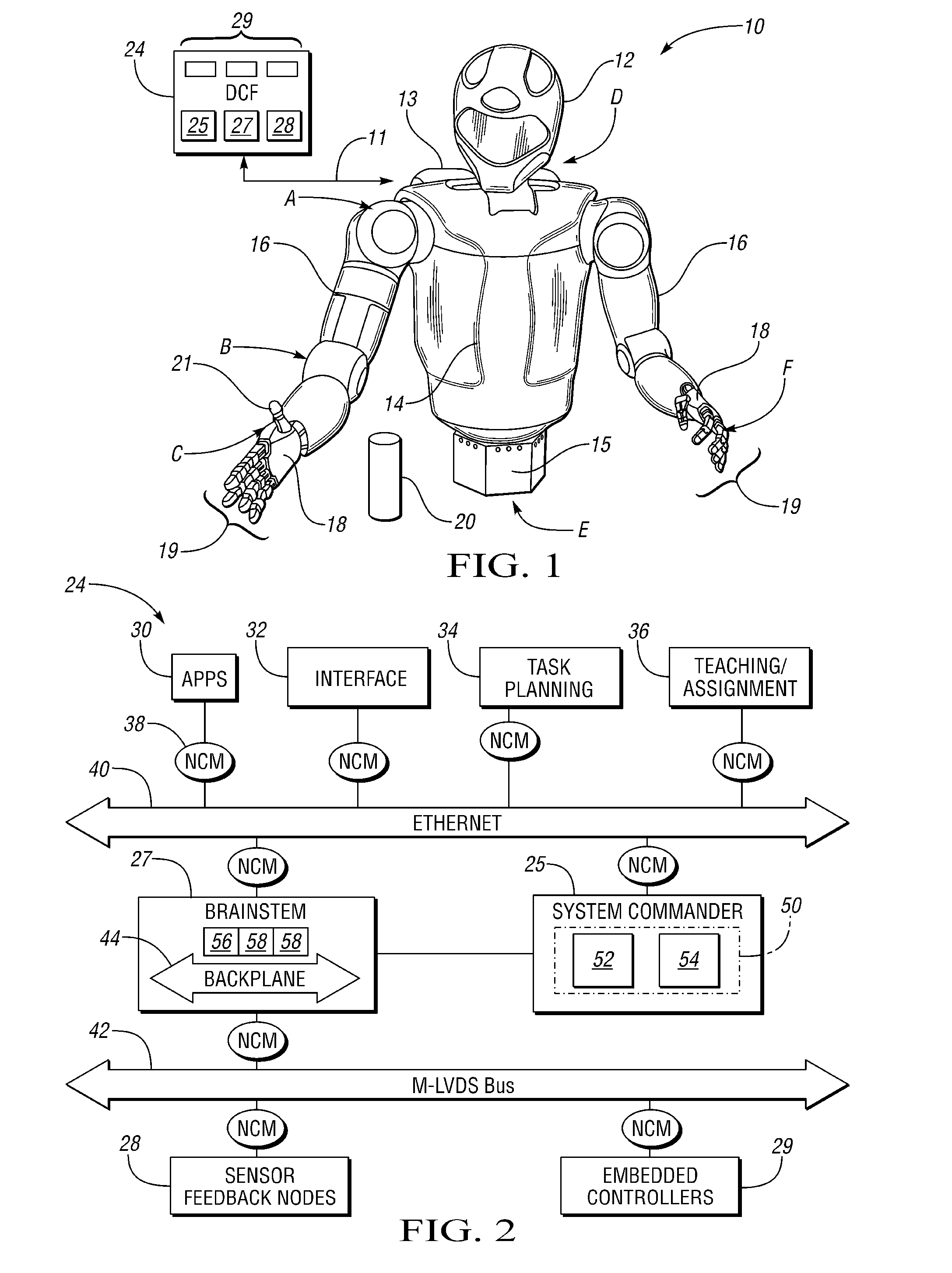
Accordingly, a distributed control framework (DCF) is provided herein for control of a dexterous humanoid robot. The DCF utilizes a series of distributed controllers communicating over multiple high-speed networks, along with a centralized abstraction layer for centralizing and abstracting all of the control and feedback data required for control of the motion and other functions of the robot. Seamless interfacing of the robotic components allows precise control over a wide variety of compliant robotic joints and other systems, both external and internal, including the various joint servo motors and actuators providing the motive force within and between each compliant joint of the humanoid robot.
The DCF provided herein allows for a large amount of control and feedback data to be centralized and abstracted in a single location, referred to herein as an “abstraction layer”, for easy cross-network data manipulation, storage, and retrieval. The hardware and control nodes can be dynamically configured, and robot functionality may be easily scaled, without requiring complex programming code compilation or state machine changes. That is, by decentralizing the DCF, the individual command modules may be easily introduced and removed in an ad hoc manner as needed to provide the required robotic functionality.

Problems solved by technology

Such a system may perform in a progressively inefficient manner in response to increasing degrees of freedom and related control complexity.

Method used


Image

  • Framework and method for controlling a robotic system using a distributed computer network
  • Framework and method for controlling a robotic system using a distributed computer network

Examples


Embodiment Construction

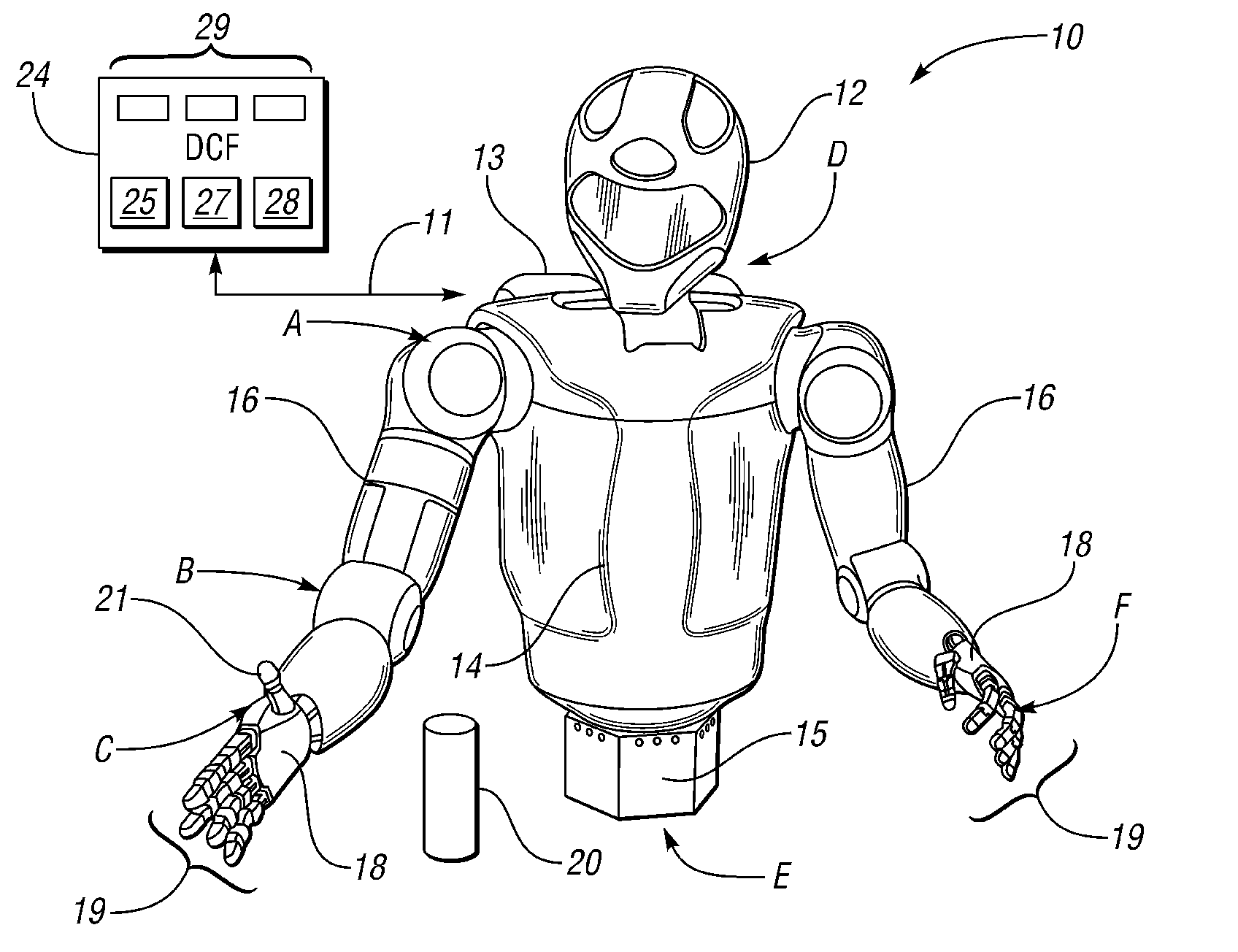
With reference to the drawings, wherein like reference numbers refer to the same or similar components throughout the several views, FIG. 1 shows a dexterous humanoid robot 10 adapted to perform one or more tasks with multiple degrees of freedom (DOF). According to one embodiment, the robot 10 is configured with a plurality of independently and interdependently-moveable compliant robotic joints, such as but not limited to a shoulder joint (arrow A), an elbow joint (arrow B), a wrist joint (arrow C), a neck joint (arrow D), and a waist joint (arrow E), as well as the various finger joints (arrow F) positioned between the phalanges of each robotic finger 19.

Each robotic joint may have one or more DOF. For example, certain joints such as the shoulder joint (arrow A), elbow joint (arrow B), and wrist joint (arrow C) may have at least two DOF in the form of pitch and roll. Likewise, the neck joint (arrow D) may have at least three DOF, while the waist and wrist (arrows E and C, respectiv...


PUM


Abstract

A robotic system for performing an autonomous task includes a humanoid robot having a plurality of compliant robotic joints, actuators, and other integrated system devices that are controllable in response to control data from various control points, and having sensors for measuring feedback data at the control points. The system includes a multi-level distributed control framework (DCF) for controlling the integrated system components over multiple high-speed communication networks. The DCF has a plurality of first controllers each embedded in a respective one of the integrated system components, e.g., the robotic joints, a second controller coordinating the components via the first controllers, and a third controller for transmitting a signal commanding performance of the autonomous task to the second controller. The DCF virtually centralizes all of the control data and the feedback data in a single location to facilitate control of the robot across the multiple communication networks.

Description

TECHNICAL FIELDThe present invention relates to the control of a humanoid robot using a distributed computer network of flexible computational modules or control nodes.BACKGROUND OF THE INVENTIONRobots are devices that are able to manipulate objects using a series of rigid links, which in turn are interconnected via articulations or actuator-driven robotic joints, e.g., electric, pneumatic, etc. Each joint in a typical robot represents an independent control variable, also referred to as a degree of freedom (DOF). End-effectors are the particular links used for performing a task at hand, e.g., grasping a work tool or an object. Therefore, precise motion control of a robot may be organized by the level of task specification: object level control, i.e., the ability to control the behavior of an object held in a single or cooperative grasp of a robot, end-effector control, and joint level control. Collectively, the various control levels cooperate to achieve the required robotic mobili...

Claims


Application Information

Patent Timeline
IPC IPC(8): G06F19/00
CPCB25J9/161G05B2219/33218G05B19/4148G05B19/4141
Inventor SANDERS, ADAM M.BARAJAS, LEANDRO G.PERMENTER, FRANK NOBLESTRAWSER, PHILIP A.
Owner NASA
Learn More