Heat exchange system

a technology of heat exchange system and heat exchange plate, which is applied in the direction of heating type, heating apparatus, domestic cooling apparatus, etc., can solve the problems of large wind resistance, affecting blowing effect, low efficiency, etc., and achieves small fluctuation in torsion, stable operation, and large rotational inertia

Inactive Publication Date: 2011-03-31
ZHONGSHAN BROAD OCEAN
View PDF15 Cites 3 Cited by
  • Summary
  • Abstract
  • Description
  • Claims
  • Application Information

AI Technical Summary

Benefits of technology

[0018]1) the blower uses the external rotor axial fan, the rotor thereof features large rotational inertia, small fluctuation in torsion, and stable operation, and the wind blade is close to the exhaust outlet and has a low wind pressure coefficient, small wind resistance, and high efficiency, which causes the external rotor axial fan to blow large amount of wind from the exhaust outlet of the box and thus improving blowing effect; 2) the heat exchange system features high overall efficiency and low power consumption, and meets requirement of the current society for energy conservation and environmental protection; 3) the wind blade is an equal-width blade with a large area and in the vicinity of the exhaust outlet of the box, and thus greatly improving inducing capacity of the external rotor axial fan, and blowing effect of the heat exchange system; 4) the annular cylinder on the support is fit on a housing of the rotor of the external rotor motor, and the inner wall of the annular cylinder is interference fit with the outer wall of the rotor, which make the invention have simple assembling, reliable connection, high production efficiency, low processing difficulty, and reduced production cost; 5) the external rotor axial fan is combined and features simple installation and disassembly, and the external rotor motor and the wind blade can be transported separated, which reduces transportation cost; 6) by using the external rotor axial fan, overall volume of the heat exchange system and system cost are reduced.

Problems solved by technology

Problems with the system are: 1) rotational inertia of the drive motor 7 of the blower 2 is small, the wind blade 9 of the blow 2 is far away from the exhaust outlet 6, and thus having a high wind pressure coefficient, large wind resistance, and low efficiency, which causes the blower 2 to blow small amount of wind from the exhaust outlet 6 of the box 4, and thus an ideal blowing effect cannot be facilitated; 2) the drive motor 7 of the blower 2 has large fluctuation in rotating torsion, namely large resonance, which causes the wind blade 9 or the wind wheel to rotate unstably, and affects blowing effects; 3) the heat exchange system employing the blower structure is low efficient and power consuming, and cannot meet requirement of the current society for energy conservation and environmental protection.

Method used


Image

  • Heat exchange system
  • Heat exchange system
  • Heat exchange system

Examples


Embodiment Construction

[0025]Further description of the invention will be given below in conjunction with specific embodiments and accompanying drawings.

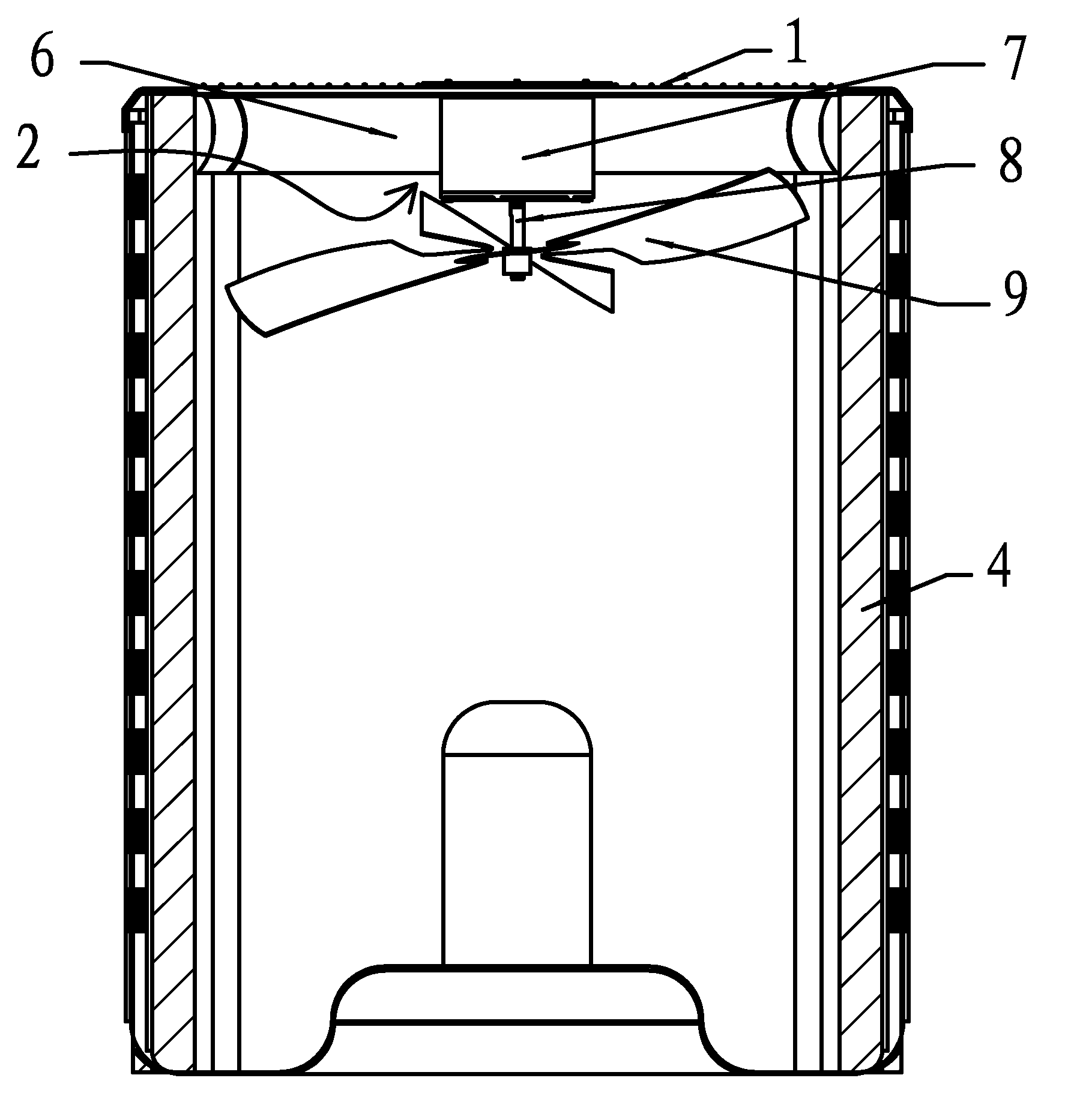
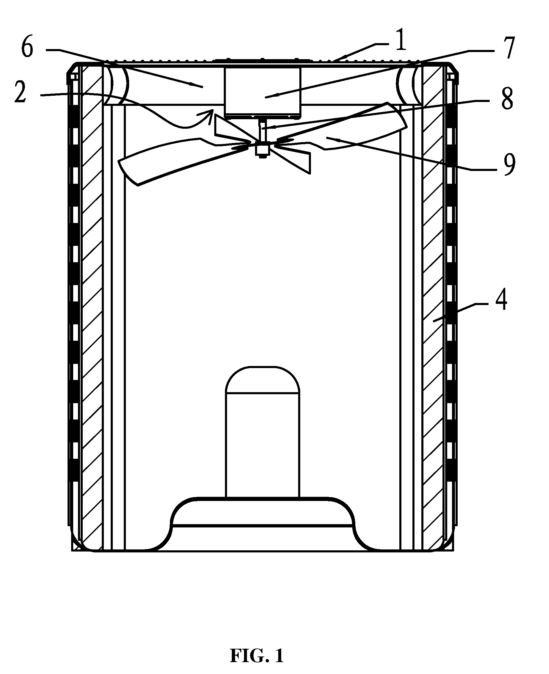
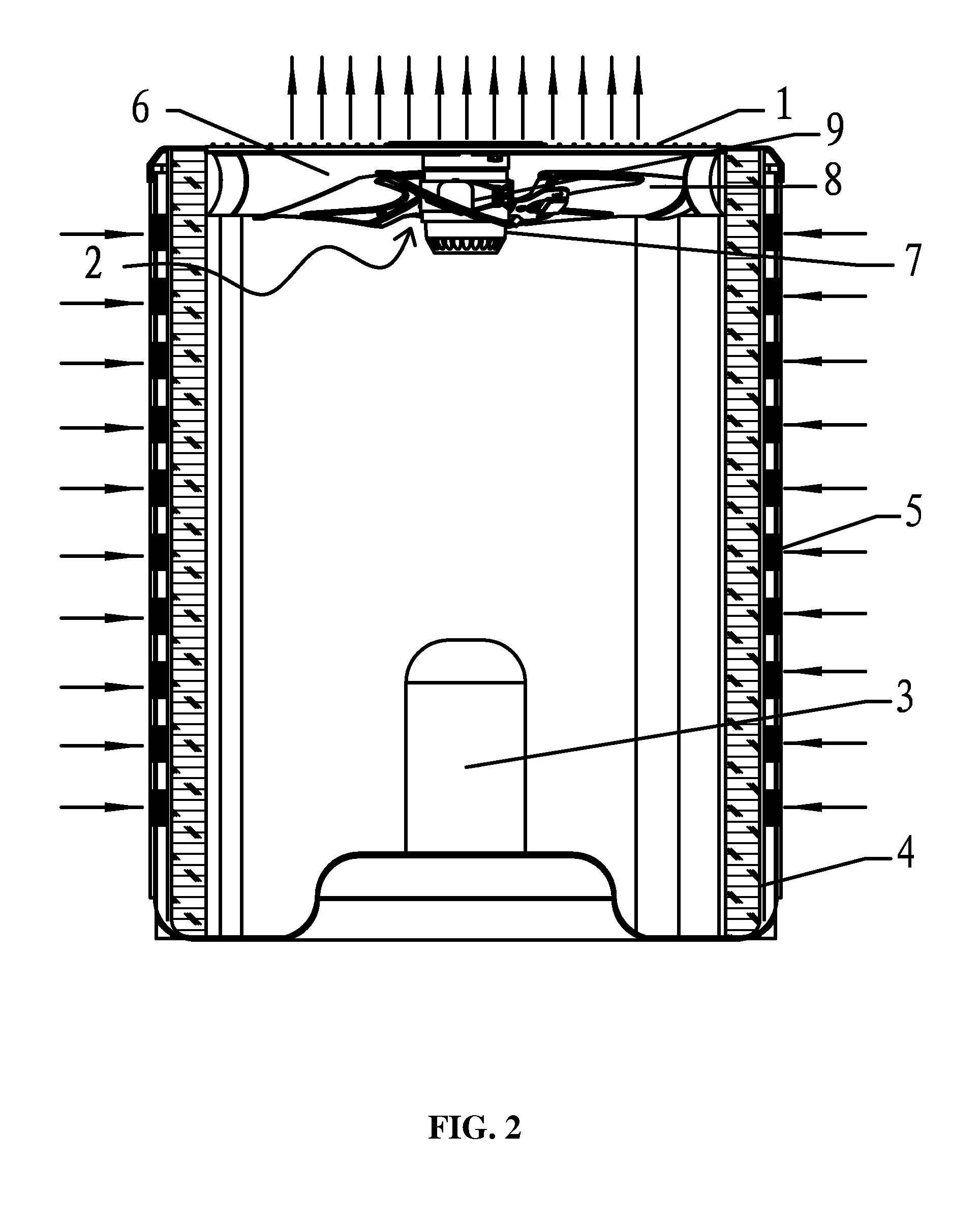
[0026]As shown in FIGS. 2, 3 and 4, a heat exchange system of the invention comprises multiple grids 1, a blower 2, a compressor 3, and a box 4 having multiple exhaust inlets 5 on the side thereof. The grid 1 is disposed at an exhaust outlet 6 of the box 4, the blower 2 is disposed in the box 4 and below the grid 1, the compressor 3 is disposed on bottom surface in the box 4. The blower 2 is an external rotor axial fan, and comprises an external rotor motor 7 and a wind blade 8, and the wind blade 8 is disposed outside a rotor 71 of the external rotor motor 7.

[0027]The wind blade 8 is disposed outside the rotor 71 of the external rotor motor 7 via a support 9, the support 9 comprises an annular cylinder 91, and multiple mounting feet 92 extending from the annular cylinder 91, the wind blade 8 is disposed on the mounting foot 92, and the annular cylinder 9...


PUM


Abstract

A heat exchange system of the invention includes at least multiple grids, a blower including an external rotor motor and a wind blade, a compressor, and a box having multiple exhaust inlets. The exhaust inlets are disposed on the side of the box. The grid is disposed at an exhaust outlet of the box. The blower is disposed in the box and below the grid. The compressor is disposed on bottom surface in the box. The blower is an external rotor axial fan, and the wind blade is disposed outside a rotor of the external rotor motor. The heat exchange system of the invention features simple structure, low cost, large air output, and good blowing effect, and is highly efficient and power-saving.

Description

CROSS-REFERENCE TO RELATED APPLICATIONS[0001]Pursuant to 35 U.S.C. §119 and the Paris Convention Treaty, this application claims the benefit of Chinese Patent Application No. 200920236976.3 filed on Sep. 30, 2009, the contents of which are incorporated herein by reference.BACKGROUND OF THE INVENTION[0002]1. Field of the Invention[0003]The invention relates to a heat exchange system.[0004]2. Description of the Related Art[0005]FIG. 1 is a schematic view of a heat exchange system in the related art. In this heat exchange system of an outdoor fan unit for an air conditioner, multiple grids 1 are disposed at an exhaust outlet 6 of a box 4, a blower 2 is disposed in the box 4 and below the grid 1, and the blower 2 comprises a drive motor 7, and a wind blade 9 or a wind wheel disposed on a motor shaft 8 of the drive motor 7. Problems with the system are: 1) rotational inertia of the drive motor 7 of the blower 2 is small, the wind blade 9 of the blow 2 is far away from the exhaust outlet ...

Claims


Application Information

Patent Timeline
Patent Type & Authority Applications(United States)
IPC IPC(8): F25D17/06
CPCF24F1/50F24F1/38
Inventor WANG, XIONGCHENG
Owner ZHONGSHAN BROAD OCEAN
Why Eureka
Try Eureka