Modular climate change tarp system

a technology of climate change and tarps, applied in the field of modular systems, can solve the problems of inconvenient installation, and inability to meet stringent requirements,

Inactive Publication Date: 2011-03-31
ICS GRP
View PDF39 Cites 13 Cited by
  • Summary
  • Abstract
  • Description
  • Claims
  • Application Information

AI Technical Summary

Benefits of technology

[0010]It is an object of the present invention to obviate or mitigate at least one disadva...

Problems solved by technology

These operations may be time consuming and inefficient in both set up and operation.
These stringent requirements can be difficult to meet in times of cold or hot temperatures.
One challenge is that the makeshift enclosure (such as hoarding) may be susceptible to wind damage.
Another challenge is that the cold air can be very dry, and once heated that very dry hot air can pull moisture from the poured conc...

Method used


Image

  • Modular climate change tarp system
  • Modular climate change tarp system
  • Modular climate change tarp system

Examples


Embodiment Construction

[0038]Generally, the present invention provides a modular system for stand-alone portable management of heating, cooling, temperature maintenance, insulation, and vapour control.

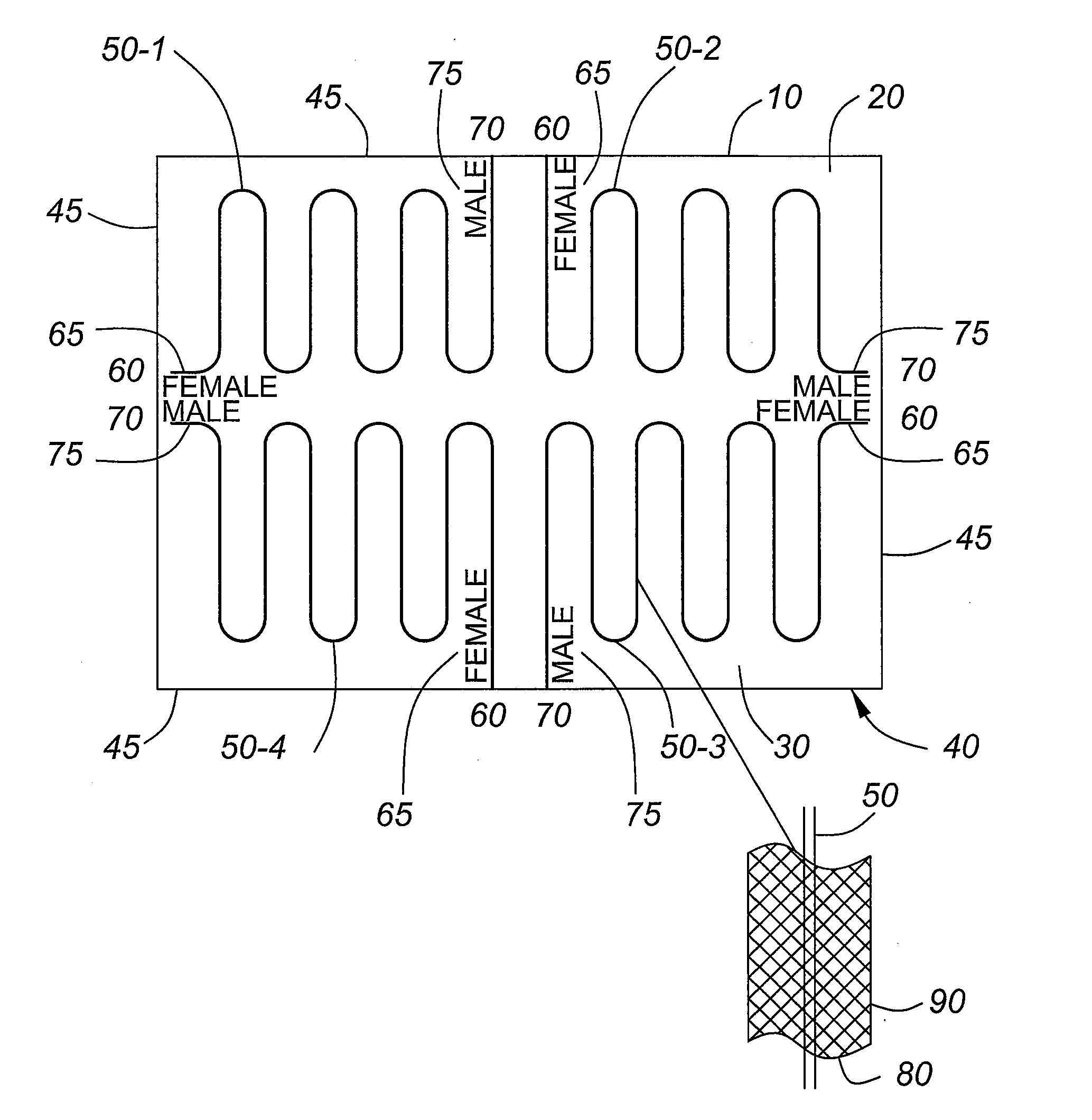
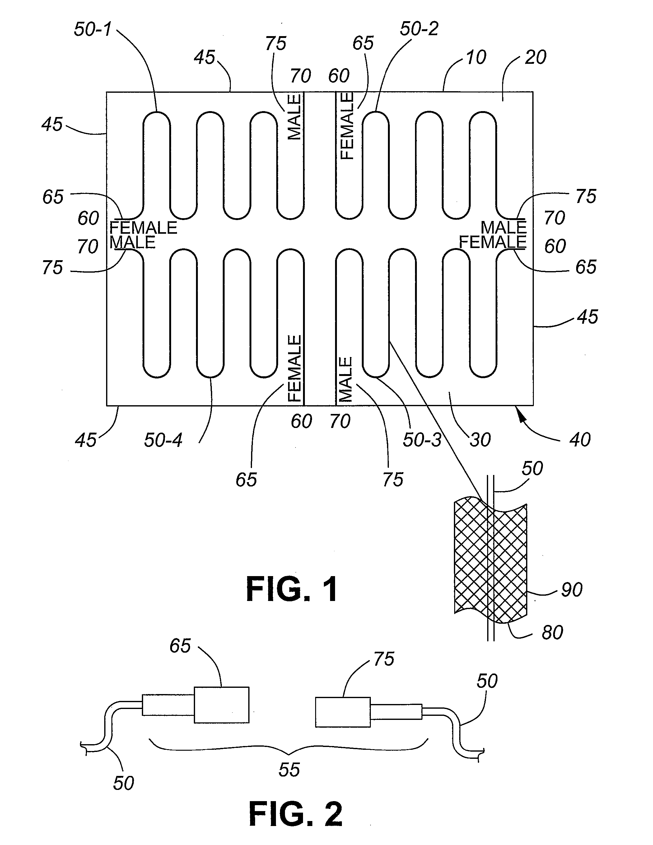
[0039]Referring to FIG. 1, a surface member 10 of the present invention includes a sheet 20 having a first side 30 and a second side 40. At least three thermal conduits 50 (four thermal conduits 50 shown as 50-1, 50-2, 50-3, and 50-4) extending from an inlet 60 at one edge 45 to an outlet 70 at an adjacent edge is attached to the first side 30 (shown), the second side 40 (not shown), or both the first side 30 and the second side 40 (not shown). The surface member 10 is a modular integration of the thermal conduit 50 and the sheet 20, and provide a variety of functions including heat transfer, insulation (heat transfer reduction or inhibition), and vapor barrier. The first side 30 or the second side 40 or both may be heat reflective, for example light colored, such as white, silver, or mirrored, or may be hea...


PUM

PropertyMeasurementUnit
Flexibilityaaaaaaaaaa
Thermal propertiesaaaaaaaaaa

Abstract

A heat transfer system having a flexible surface member having a first side and a second side, forming a heat transfer surface, and two or more thermal conduits, spaced apart and extending across a portion of the heat transfer surface, the two or more thermal conduits adapted to receive a thermal media to form a heat source (heating) or heat sink (cooling) across the heat transfer surface. The flexible surface member may have a plurality of edge regions, the two or more thermal conduits extending between edge regions, such as adjacent edge regions or opposing edge regions. The flexible surface member may have a plurality of corner regions, the two or more thermal conduits extending between corner regions, such as adjacent corner regions or opposing corner regions.

Description

FIELD OF THE INVENTION[0001]The present invention relates generally to a portable heat transfer surface. More particularly, the present invention relates to a modular system including a flexible membrane associated with connectable hoses adapted to circulate a thermal media.BACKGROUND OF THE INVENTION[0002]In industrial construction such as earthwork / earth moving, construction of oil & gas pipelines, maintenance of vessels or tanks, building construction, and other operations require heating or cooling in order to provide for operations to safely and efficiently continue in adverse climates or adverse ambient conditions. The equipment, work, and personnel may require protection from the ambient conditions and / or the localized ambient conditions may require management.[0003]In cold climates, the topsoil or at least some depth of the earth's surface may freeze which may inhibit earthwork, such as digging or trenching. Traditionally thawing or warming of the ground may be accomplished ...

Claims


Application Information

Patent Timeline
IPC IPC(8): F24J3/08F28F7/00F28D15/00
CPCF24D3/125F28F2210/10F28D1/035F28F2255/02F28F2210/02F28F21/062F24D3/12F24D2220/2081Y02B30/00
Inventor BRUMMITT, DALEKACHUR, KENGAMRACY, RICKHENDERSON, WILLIAM DANLOEPPKY, STEVENAGY, DUANE
Owner ICS GRP
Why Eureka
Try Eureka