
Rotary evaporator

Active Publication Date: 2011-03-31
ECODYST
View PDF12 Cites 30 Cited by
  • Summary
  • Abstract
  • Description
  • Claims
  • Application Information

AI Technical Summary

Benefits of technology

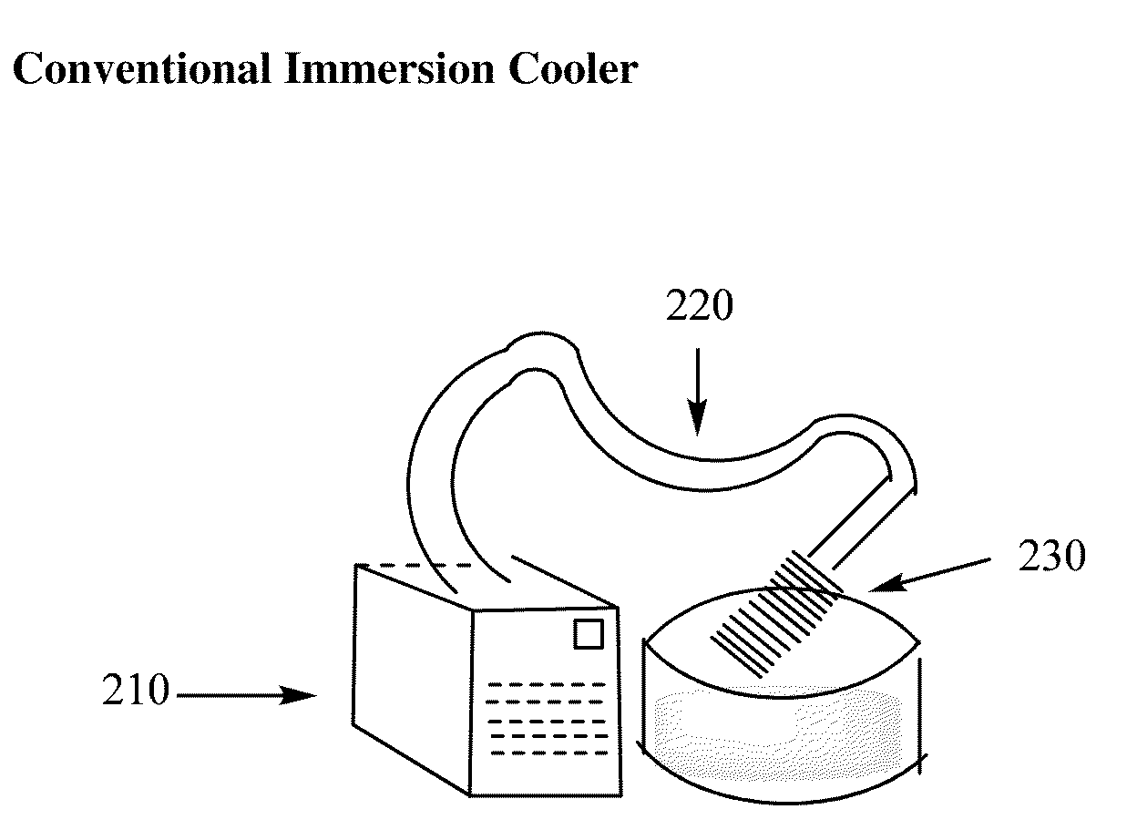
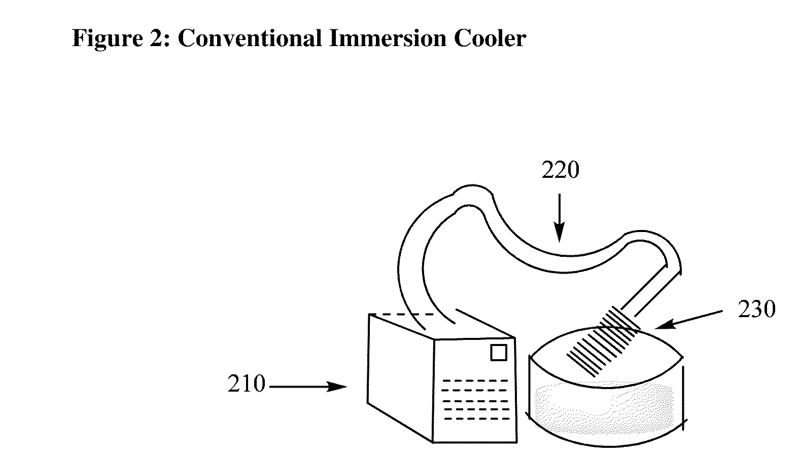
[0011]The condensers, such as dry ice condensers, are capable of receiving, or are adapted to receive, the cooling coil portion of an immersion cooler. The immersion cooler provides efficient cooling capacity while eliminating the hassles associated with chemical refrigerants such as dry ice and dry ice / acetone mixtures. The immersion cooler includes a base unit that cools a recirculating gas or liquid, a cooling coil through which the cooled, recirculating gas or liquid flows, and an insulated hose that transports the recirculating gas or liquid to and from the base unit and a cooling coil. The cooling coil can be appropriately sized to fit the condenser, or can be equipped with a plug that fits around the insulated hose, and within the top portion of the condenser much like a cork fits inside the top of a bottle, or a one-hole stopper fits inside of a hole in a round-bottom flask.
[0014]In those embodiments where the immersion cooler and rotary evaporator are provided as a single unitary device, and the rotary evaporator and immersion cooler are physically attached to one another, it can be difficult to raise and lower the combination of the rotary evaporate and immersion cooler out of a water bath in the same way that the rotary evaporator is typically raised and lowered out of a water bath. Accordingly, the present invention provides various embodiments for removing the flask from the water bath, or for removing heat from the water bath, without having to raise or lower the entire unit.
[0016]In another embodiment, the level of fluid that heats the flask is adjusted by using a reservoir beneath the water bath, such that the heating fluid, such as hot water or hot oil, can be removed by lowering the level of heating fluid to a position below the flask.

Problems solved by technology

Users frequently leave the water flowing through the condenser throughout the day, which results in large volumes of waste water.
To only use a water-cooled condenser might create an environmental issue, as a significant volume of volatile organic solvent would not be collected, and enter into the environment.
This can be a burden to the scientists, who have to replace the dry ice in their condensers throughout the day, particularly where a laboratory has a significant number of scientists accessing the same source of dry ice.
One limitation of the chillers is that the fluids tend to be only marginally cooler than water (i.e., they are typically limited to fluids that are cooled to around −15 to −20° C.).
Another limitation is that they can be extremely expensive.

Method used


Image

  • Rotary evaporator
  • Rotary evaporator
  • Rotary evaporator

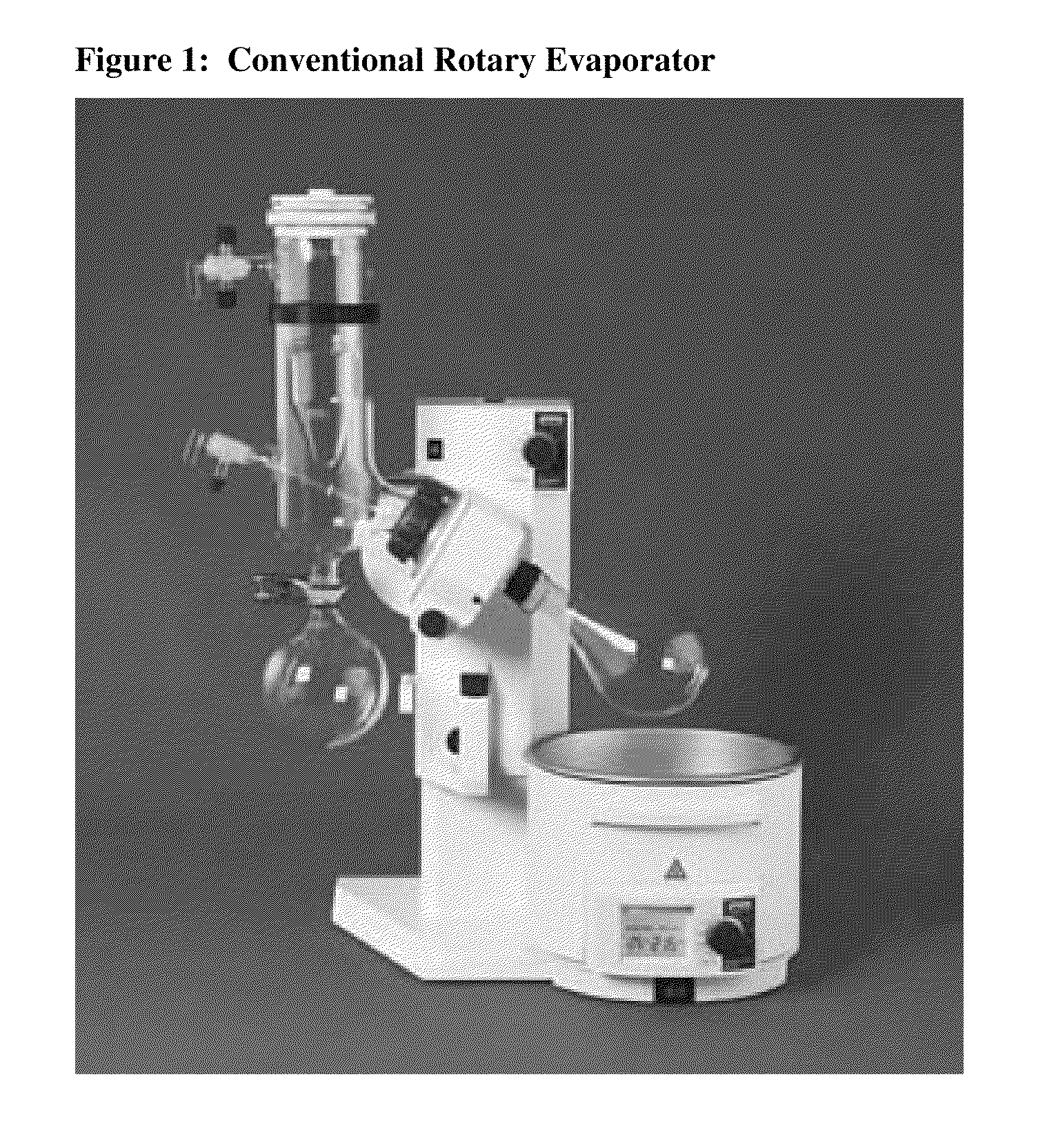
Examples


Embodiment Construction

[0029]A rotary evaporator capable of cooling evaporated solvents without using dry ice trap, a continuous flow of water, or a recirculating chiller, is disclosed. The evaporator uses mechanically refrigerated cooling / freezing technology to provide a cool reservoir capable of condensing vapors arising from such activities as solvent evaporation. By avoiding the waste of a continuous flow of water, or the use of dry ice and compatible solvents such as acetone and isopropyl alcohol, the device is environmentally beneficial.

[0030]The rotary evaporator described herein replaces the dry ice cooling systems used in conventional rotary evaporators with a permanent cooling technology based on refrigerant / coil cooling technology.

[0031]The rotary evaporator includes the usual components of a rotary evaporator, but also includes an immersion cooler attached to the condenser, where the immersion cooler includes a base unit (condensing unit), a cooling coil, and an insulated hose connecting the c...


PUM

PropertyMeasurementUnit
Flexibilityaaaaaaaaaa

Abstract

A rotary evaporator comprising a motor, a rotary joint movably inserted to a motor rotor of the motor by a sleeve in an axial direction, a collection flask attached to the rotary joint at one end of the joint, with a condenser attached to the other end of the joint. The condenser is adapted to receive a cooling coil from an immersion cooler. The cooling coil is attached to the base unit of the immersion cooler via an insulated hose. The rotary evaporator is adapted to provide various ways to remove heat from the flask in the water bath, whether by mechanically lowering the water bath, dropping fluid from the bath into an underlying reservoir, or raising and lowering the rotary evaporator out of the bath. Where the rotary evaporator is raised and lowered, the immersion cooler can remain in place if the hose connecting the base unit to the cooling coil is sufficiently long, or the condenser includes a flexible portion that accommodates the upward and downward movement.

Description

FIELD OF THE INVENTION[0001]The present invention relates to a rotary evaporator, and relates more particularly to a combination of a rotary evaporator and an immersion cooler that can improve the environmental impact of rotary evaporators in the laboratory.BACKGROUND OF THE INVENTION[0002]Rotary evaporators are in widespread use in virtually every laboratory in the world, for removing solvents from organic and inorganic solutions, to yield a liquid or solid product.[0003]The evaporators work by placing a sample in a round-bottom flask, typically a pear-shaped flask, which spins on an axis at an angle while sitting in a water bath. The flask is attached to a motor, which includes a rotary joint that enables the flask to spin, while permitting the evaporated solvent to flow through the joint (vapor duct) and come into contact with one or more condensers. The condenser(s) cool the vapor, and the resulting cooled vapor (i.e., liquid) then flows down to a flask below the condenser, wher...

Claims


Application Information

Patent Timeline
IPC IPC(8): B01D5/00
CPCB01D1/0052B01D1/228B01D5/006B01D3/10B01D3/085Y10S203/02
Inventor ADJABENG, GEORGE M.
Owner ECODYST
Learn More