Adjustable Multimode Lightfield Imaging System

a multi-mode lightfield imaging and adjustment technology, applied in the field of multi-mode imaging systems, can solve the problems of large and complex systems, difficult to acquire additional information, and difficult to capture the second spatial dimension of objects

Inactive Publication Date: 2011-03-31
RICOH KK
View PDF4 Cites 41 Cited by
  • Summary
  • Abstract
  • Description
  • Claims
  • Application Information

AI Technical Summary

Benefits of technology

[0010]The present invention overcomes the limitations of the prior art by providing an adjustable multimode lightfield imaging system. A non-homogeneous filter module is positioned at or near the ...

Problems solved by technology

Acquiring this additional information can be difficult since most commercially available detector arrays spatially segment the incoming image into a two-dimensional image signal.
However, the resulting systems can be large and complicated.
However, it is difficult to also capture the second spatial dimension of the object.
This architecture has the disadvantage that the dispersive element is typically applied to either a collimated beam or at an intermediate ...

Method used


Image

  • Adjustable Multimode Lightfield Imaging System
  • Adjustable Multimode Lightfield Imaging System
  • Adjustable Multimode Lightfield Imaging System

Examples


Embodiment Construction

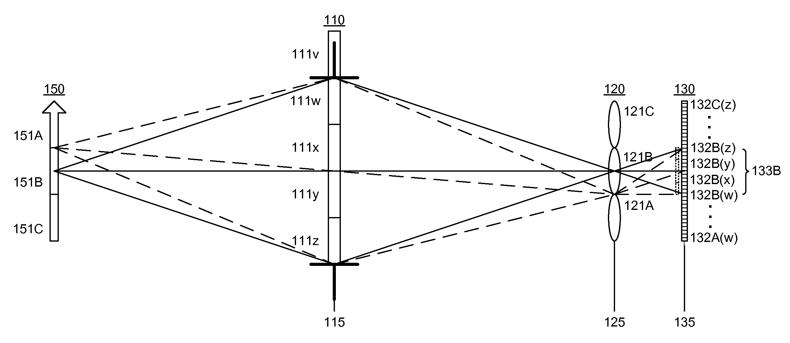
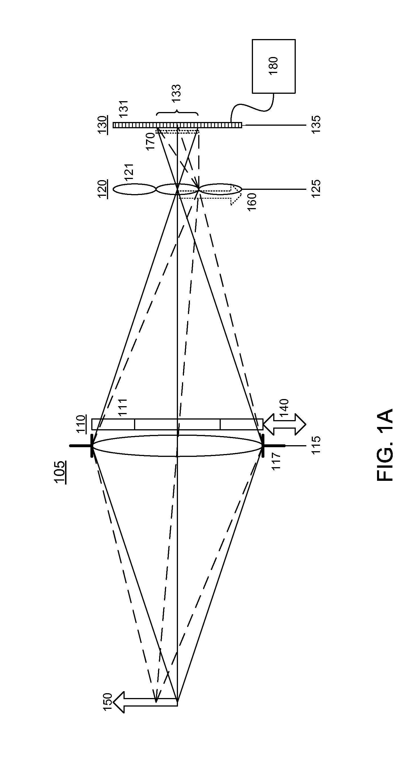
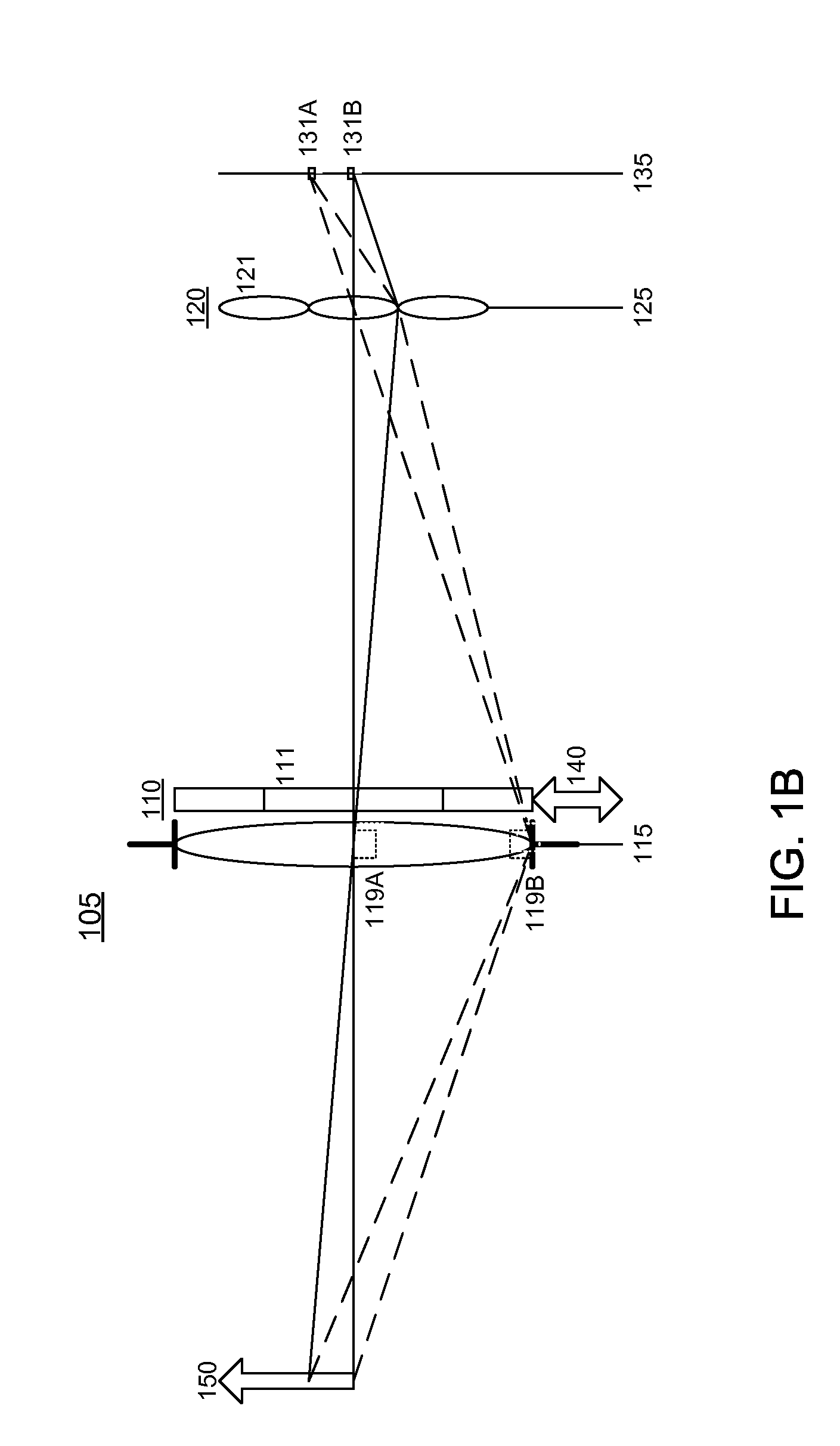
[0026]FIGS. 1A-1C are diagrams of an adjustable multimode lightfield imaging system according to the invention. The system captures a multimode image of an object 150. The multimode lightfield imaging system includes an image-forming optical module 105, which in FIG. 1 is represented by a single lens element although it is understood that the optical module 105 could contain multiple elements and / or non-lens elements (e.g., mirrors). The optical module 105 forms an optical image 160 of object 150. The optical image 160 is formed at an image plane 125 of the optical module 105. The optical module 105 has an aperture 117 and aperture plane 115, which in FIG. 1 is represented by an aperture stop co-located with the single lens element. In more complex optical modules 105, the aperture 117 and aperture plane 115 need not be co-located with any of the optical elements within the optical module.

[0027]In a conventional imaging system, a detector array would be located at image plane 125 to...


PUM


Abstract

An adjustable multimode lightfield imaging system. A non-homogeneous filter module is positioned at the aperture plane of the lightfield imaging system and provides the multimode capability. The filter module can be moved relative to the imaging system, thus allowing adjustment of the multimode capability.

Description

BACKGROUND OF THE INVENTION[0001]1. Field of the Invention[0002]This invention relates generally to multimode imaging systems using filter modules, and, more particularly, to such systems where the multimode characteristics can be changed by a relative motion of the filter module.[0003]2. Description of the Related Art[0004]A multimode imaging system is an imaging system that can capture information beyond the usual spatial information acquired by conventional imaging systems (e.g., those based on RGB Bayer patterns). For example, a multimode imaging system might acquire additional spectral information (multispectral and hyperspectral systems) to be used for spectral analysis or identification of substances. Multimode imaging systems might also capture information about the polarization of a scene, or even provide a higher dynamic range than that provided by the inherent capability of the detector array.[0005]Acquiring this additional information can be difficult since most commerci...

Claims


Application Information

Patent Timeline
IPC IPC(8): H01L31/0232
CPCG01J1/0492G01J3/0237G01J3/2823G01N21/255G01N21/21G01N21/251G01J3/36
Inventor BERKNER, KATHRINROBINSON, M. DIRKKE, JUN
Owner RICOH KK
Why Eureka
Try Eureka