Field emission device and method of operating the same

a field emission and field technology, applied in the direction of electric variable regulation, process and machine control, instruments, etc., can solve the problem of difficulty in implementing rapid pulse driving

Active Publication Date: 2011-03-31
ELECTRONICS & TELECOMM RES INST
View PDF3 Cites 11 Cited by
  • Summary
  • Abstract
  • Description
  • Claims
  • Application Information

AI Technical Summary

Problems solved by technology

In other words, since the field emission current cannot be immediately blocked even thou...

Method used


Image

  • Field emission device and method of operating the same
  • Field emission device and method of operating the same
  • Field emission device and method of operating the same

Examples


Embodiment Construction

[0034]Hereinafter, the present invention will be described with reference to the accompanying drawings in detail. This invention may, however, be embodied in different forms and should not be construed as limited to the embodiments set forth herein. Rather, these embodiments are provided so that this disclosure will be thorough and complete, and will fully convey the scope of the invention to those skilled in the art. Like numbers refer to like elements throughout the specification. In the drawings, the thickness of layers and regions are exaggerated for clarity.

[0035]Throughout the specification, when a part “includes” an element, the part may include, not remove, another element, unless otherwise defined.

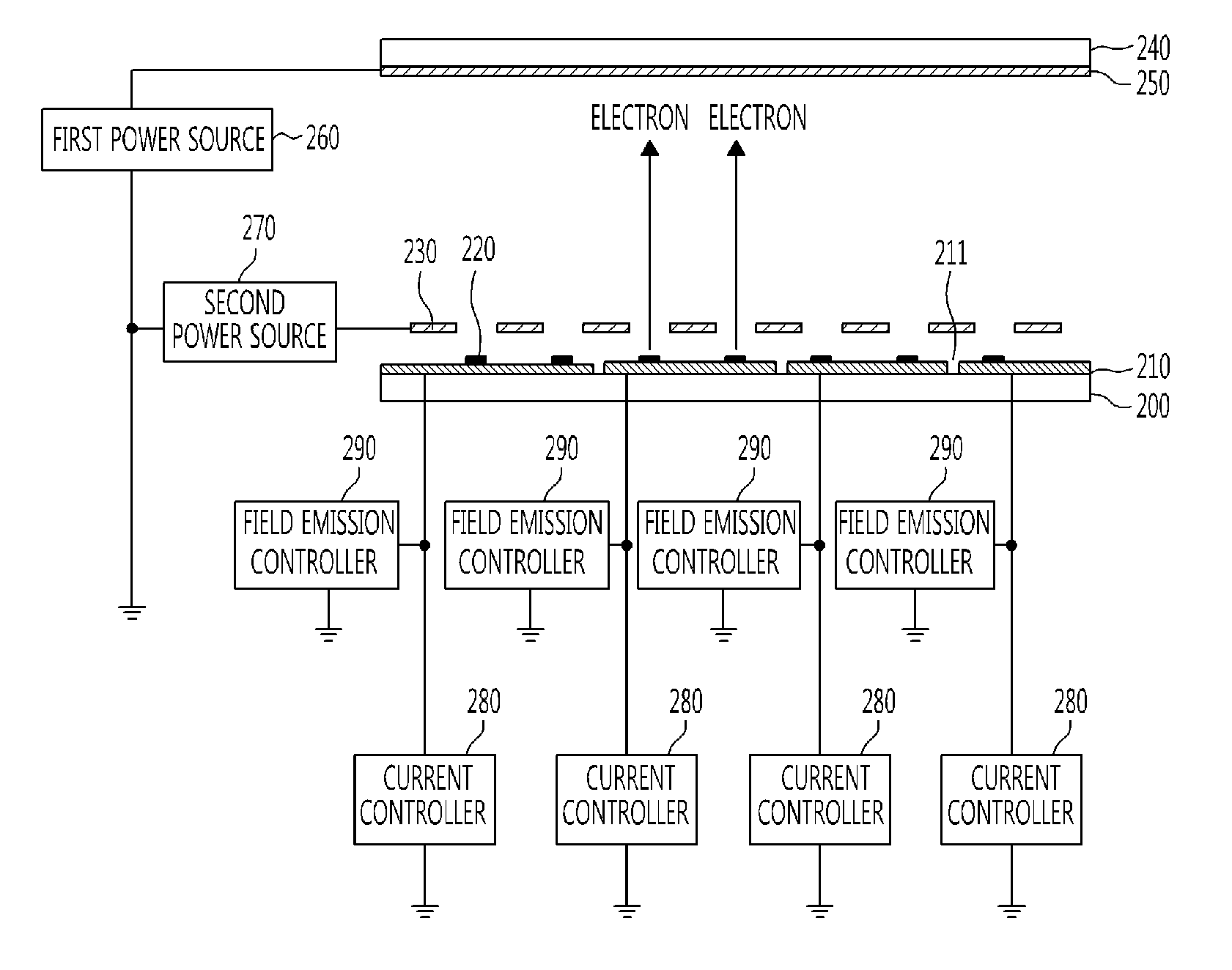
[0036]FIG. 3 is a diagram showing a structure of a field emission device according to an exemplary embodiment of the present invention, and particularly shows a structure of a triode field emission device. For clarity, the following description will focus on electrodes, disregardi...


PUM


Abstract

Provided are a field emission device enabling rapid pulse operation and a method of operating the same. The field emission device includes a cathode electrode including a field emission source, an anode electrode disposed to face the cathode electrode and accelerating electrons emitted from the field emission source, a current controller controlling field emission current flowing through the cathode electrode, and a field emission controller applying a pull-up voltage to the cathode electrode when the current controller is turned off.

Description

CROSS-REFERENCE TO RELATED APPLICATION[0001]This application claims priority to and the benefit of Korean Patent Application Nos. 10-2009-0090793 filed Sep. 25, 2009, and 10-2010-0041309 filed May 3, 2010, the disclosure of which is incorporated herein by reference in its entirety.BACKGROUND[0002]1. Field of the Invention[0003]The present invention relates to a field emission device and a method of operating the same, and more particularly, to a field emission device enabling rapid pulse operation and a method of operating the same.[0004]2. Discussion of Related Art[0005]A field emission device emits electrons from a cathode electrode by applying an electric field in a vacuum atmosphere, and is used as a field emission display (FED), a field emission lamp (FEL), a field emission X-ray, etc.[0006]Such field emission devices are classified into diode field emission devices composed of a cathode electrode and an anode electrode and triode field emission devices composed of a cathode el...

Claims


Application Information

Patent Timeline
IPC IPC(8): H05B41/36
CPCH05B33/0896H05B45/60Y02B20/30
Inventor JEONG, JIN WOOSONG, YOON HOKIM, JAE WOO
Owner ELECTRONICS & TELECOMM RES INST
Why Eureka
Try Eureka