Piezoelectric Actuator, Method of Driving Same, Liquid Ejection Apparatus and Piezoelectric Ultrasonic Osicllator

a piezoelectric actuator and actuator technology, applied in the direction of generator/motor, device material selection, printing, etc., to achieve the effect of high piezoelectric characteristics, improved driving durability, and efficient displacemen

Active Publication Date: 2011-03-31
FUJIFILM CORP
View PDF2 Cites 15 Cited by
  • Summary
  • Abstract
  • Description
  • Claims
  • Application Information

AI Technical Summary

Benefits of technology

[0034]However, the object of International Publication WO 2003 / 022582 is to displace the position of the hysteresis in the application of voltage in the reverse potential period to a position where displacement can be obtained more efficiently, and driving durability is improved by driving in a range which is not affected by deterioration of the hysteresis, based on the premise that there is no change in the maximum amount of displacement.
[0035]If it is sought to drive a piezoelectric actuator comprising a piezoelectric body having asymmetrical P-E hysteresis and high piezoelectric characteristics by using the piezoelectric characteristics to the maximum limit, then the voltage applied to the piezoelectric body is very high and a great load is placed on the piezoelectric body, which results in very rapid deterioration of the displacement. The inventors made a thorough study of driving methods which can be used to drive a piezoelectric actuator comprising a piezoelectric body having asymmetrical P-E hysteresis and high piezoelectric characteristics, while suppressing decline in the durability of the piezoelectric body, and discovered that driving durability is improved dramatically with better drive characteristics. More specifically, the present invention differs in conception from International Publication WO 2003 / 022582 in that it improves the driving durability and element reliability of a piezoelectric actuator by reducing the load applied to a piezoelectric body of this kind when the piezoelectric body is driven.
[0036]Furthermore, with a normal drive method, under conditions of high humidity and high temperature, ions present in the piezoelectric film (for example, positive lead ions) migrate to one side, which may be a cause of insulation breakdown. According to the driving method of the present invention, the driving is performed on both the positive and negative sides, and bias of the ions can be greatly restricted and therefore driving durability is improved dramatically. Such ion migration is particularly liable to occur in a piezoelectric body having a composition which is far from a stoichiometric state. Consequently, in a piezoelectric element comprising a piezoelectric body having a composition of this kind, beneficial effects of the present invention in improving driving durability are very great indeed. For example, if the piezoelectric body contains lead (Pb), then particularly beneficial effects are obtained if the lead content is greater than the stoichiometric content (in the case of a perovskite oxide, a composition where the mol ratio of lead with respect to oxygen is ⅓ or greater).
[0037]As described previously, the present invention improves the drive characteristics (removal volume) of a piezoelectric body at the same time as preventing bias in the material caused by ion migration in the piezoelectric body which occurs during driving, and therefore to differs from a method which improves drive characteristics only.
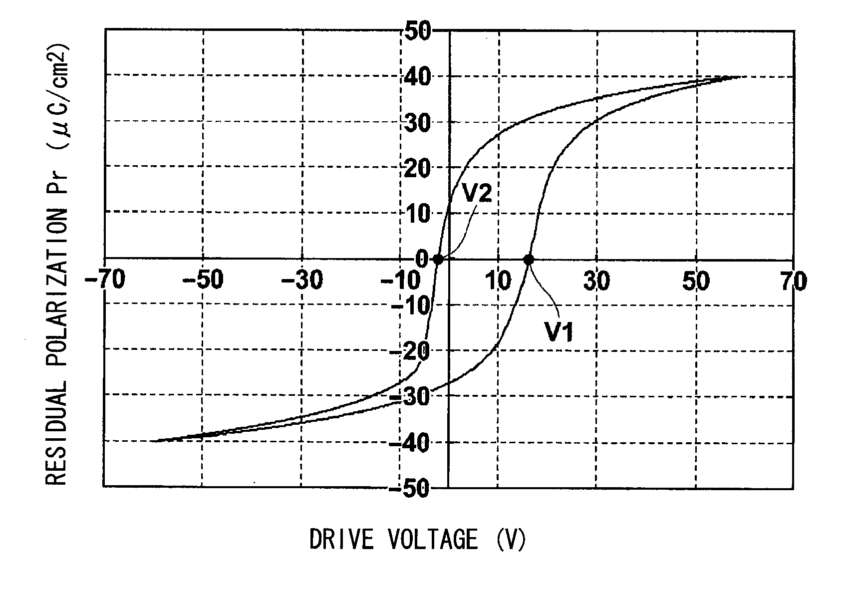
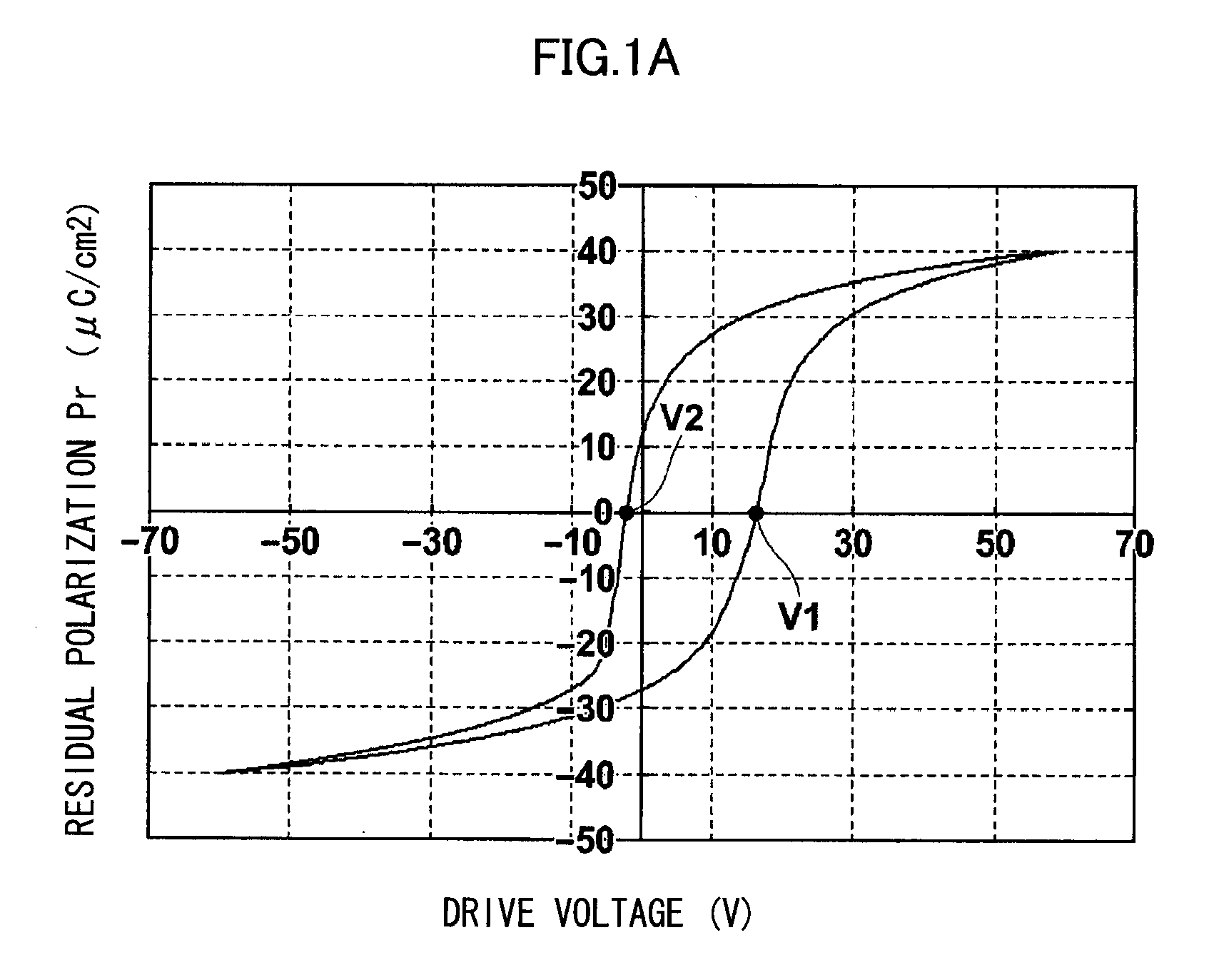
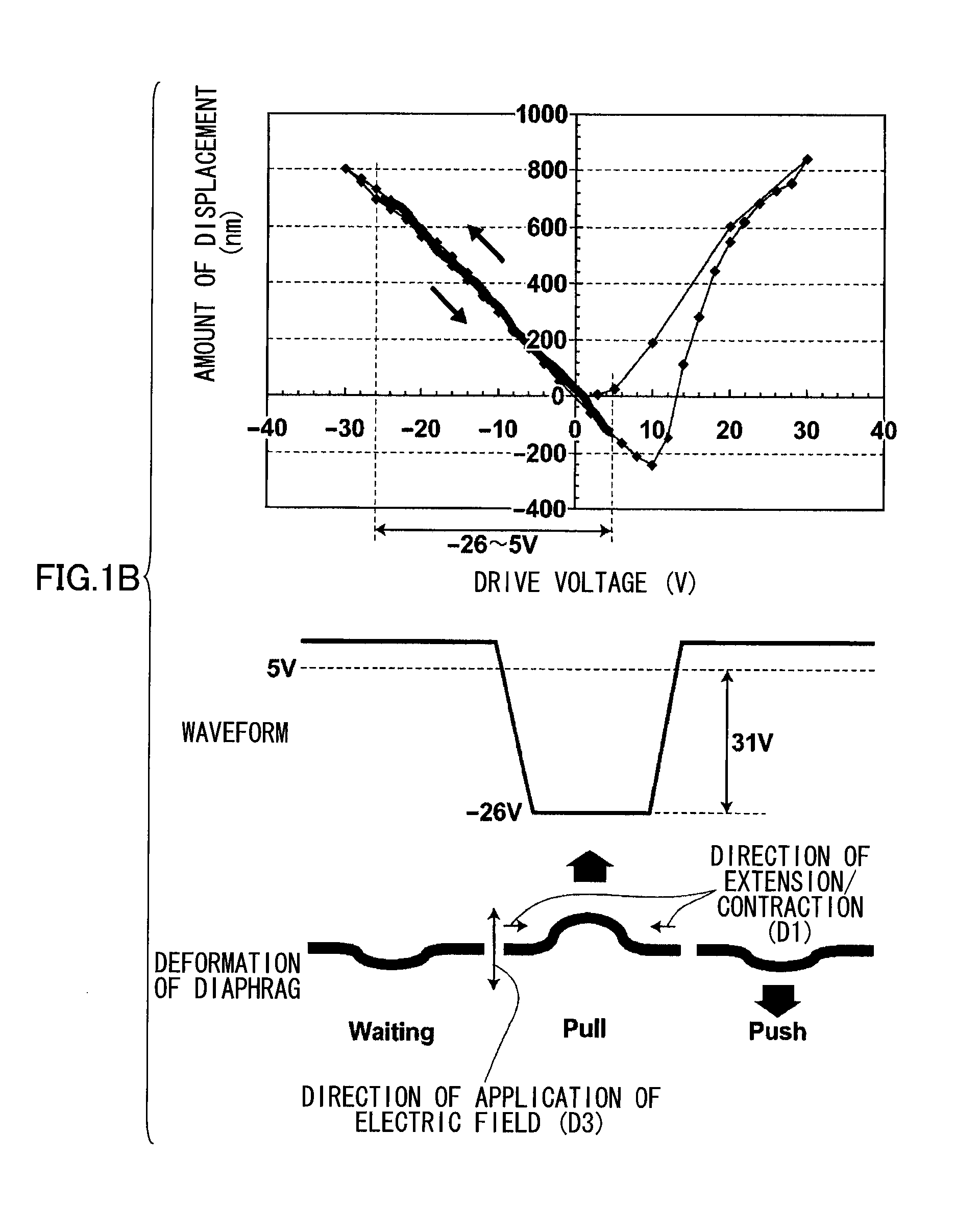
[0038]As described above, the driving method for a piezoelectric actuator according to the present invention drives a piezoelectric actuator including: a piezoelectric body having respective coercive electric field points on the negative field side and the positive field side, and asymmetrical bipolar polarization—field hysteresis characteristics in which the absolute value of the coercive electric field on the negative field side is different from the coercive electric field value on the positive field side, the piezoelectric actuator being driven between a positive drive voltage and a negative drive voltage in a range not exceeding the coercive electric field, from among the positive and negative coercive electric fields, which has the larger absolute value. According to this method, it is possible to drive an actuator at a voltage (absolute value) lower than the drive voltage required when driving is carried out by a normal driving method, and therefore it is possible to improve the driving durability and the element reliability of the piezoelectric actuator by reducing the load on the piezoelectric body.
[0039]In particular, if the driving method of the present invention is applied to an actuator comprising a piezoelectric body having voltage displacement characteristics of 10% or less linearity in the driving range, then it is possible to obtain a large amount of displacement with good efficiency, at a low drive voltage (absolute value).

Problems solved by technology

Consequently, Japanese Patent Application Publication No. 2003-243741 and Japanese Patent Application Publication No. 2008-218547 do not reduce the load on the piezoelectric body by efficient driving of a currently available piezoelectric body having asymmetrical P-E hysteresis, such as PZT or the like.
However, International Publication WO 2003 / 022582 does not describe the application of a piezoelectric actuator comprising a piezoelectric body having asymmetrical P-E hysteresis.

Method used


Image

  • Piezoelectric Actuator, Method of Driving Same, Liquid Ejection Apparatus and Piezoelectric Ultrasonic Osicllator
  • Piezoelectric Actuator, Method of Driving Same, Liquid Ejection Apparatus and Piezoelectric Ultrasonic Osicllator
  • Piezoelectric Actuator, Method of Driving Same, Liquid Ejection Apparatus and Piezoelectric Ultrasonic Osicllator

Examples


examples

[0118]Examples relating to the present invention are described below.

first example

[0119]A substrate with electrodes was prepared by successively layering a 150 nm-thick Ir lower electrode via a Ti adhesive layer, by sputtering, onto an SOI substrate in which a diaphragm structure was formed. Thereupon, a Nb-doped PZT film (Nb—PZT film) was formed to a thickness of 4 microns using a Pb1.3Zr0.43Ti0.44Nb0.13O3 sintered body as a target, in a mixed Ar / O2 atmosphere (O2 volume fraction of 1.0%) at vacuum pressure 0.5 Pa, film forming temperature 525° C., input power 500W, and substrate / target distance 60 mm

[0120]In this case, the film was deposited with the substrate in a floating state and an earth provided at a position distant from the substrate that was not located between the target and the substrate. The composition of the film thus obtained was analyzed by XRF and found to be Pb1.03Zr0.43Ti0.44Nb0.13O3.

[0121]Thereupon, an upper electrode of Pt was formed by sputtering via a Ti adhesive layer on the Nb—PZT film, and was patterned by a lift-off method to create a...

second example

[0128]Apart from adopting a target composition of Pb1.3Zr0.52Ti0.48O3, a piezoelectric actuator was manufactured similarly to the first example. The composition of the film thus obtained was analyzed by XRF and found to be Pb1.01Zr0.52Ti0.48O3. When the P-E hysteresis characteristics of the piezoelectric actuator thus obtained were measured, the bias rate was 13% (not shown in the drawings).

[0129]Furthermore, the bipolar field—displacement characteristics of the piezoelectric actuator were measured and the hysteresis shown in FIG. 7 was obtained. As shown in FIG. 7, since the displacement on the positive field side is extremely small and the lead content is low compared to the first example, then in the piezoelectric actuator having these electric field—displacement characteristics, although slight beneficial effects were obtained, it was confirmed that beneficial effects of adopting the driving method for a piezoelectric actuator according to the present invention were very small i...


PUM


Abstract

A method of driving a piezoelectric actuator including: a piezoelectric element containing a piezoelectric body having coercive field points on a negative field side and a positive field side respectively and having asymmetrical bipolar polarization—electric field hysteresis characteristics in which an absolute value of a coercive electric field on the negative field side and a coercive electric field value on the positive field side are mutually different, and a pair of electrodes for applying voltage to the piezoelectric body; and a diaphragm which externally transmits, as displacement, distortion produced in the piezoelectric body when the voltage is applied to the piezoelectric body, includes the step of driving the piezoelectric actuator between a positive drive voltage and a negative drive voltage in a range not exceeding the coercive electric field, from among the positive and negative coercive electric fields, which has the larger absolute value.

Description

BACKGROUND OF THE INVENTION[0001]1. Field of the Invention[0002]The present invention relates to a method of driving a piezoelectric actuator including a piezoelectric body which has respective coercive electric field points on a negative field side and a positive field side, and has asymmetrical bipolar polarization / field hysteresis characteristics in which an absolute value of the coercive electric field on the negative field side and the coercive electric field value on the positive field side are mutually different, and also relates to a piezoelectric actuator used in this drive method, a liquid ejection apparatus using this piezoelectric actuator, and a piezoelectric type ultrasonic oscillator.[0003]2. Description of the Related Art[0004]A piezoelectric element which comprises a piezoelectric body having piezoelectric characteristics whereby the body expands and contracts with increase and decrease in the intensity of an applied electric field, and an electrode which applies an...

Claims


Application Information

Patent Timeline
Patent Type & Authority Applications(United States)
IPC IPC(8): B41J2/045H01L41/09H01L41/18H01L41/187H01L41/22H01L41/316H01L41/39H02N2/00H02N11/00
CPCB41J2/04581B41J2/04588H01L41/0973H01L41/18H01L41/042H10N30/802H10N30/2047H10N30/8554
Inventor FUJII, TAKAMICHIHISHINUMA, YOSHIKAZUKATOH, YOSHINORIARAKAWA, TAKAMINAONO, TAKAYUKI
Owner FUJIFILM CORP
Why Eureka
Try Eureka