Imaging apparatus and method for controlling same

a diaphragm and drive position technology, applied in the direction of exposure control, instruments, television systems, etc., can solve the problems of power consumption and heating, power consumption and heat generation, and large stepping angle per step, so as to reduce electrical power required and facilitate the control of moving images

Active Publication Date: 2011-03-31
CANON KK
View PDF11 Cites 7 Cited by
  • Summary
  • Abstract
  • Description
  • Claims
  • Application Information

AI Technical Summary

Benefits of technology

[0014]According to the present invention, in an imaging apparatus that performs diaphragm driving using the stepping motor, the operation modes are switched depending on the type of a lens section, whereby a favorable moving image exposure control is carried out while reducing electrical power required for holding the diaphragm position.

Problems solved by technology

However, this is a direct current, and, if this state persists for a long time particularly when a battery is employed as the power supply, power may be consumed and heat generated despite the fact that the diaphragm is not being driven.
This particularly creates problems when a battery is employed for a power supply.
However, the rotation stepping angle per step is large, which is not suitable when highly accurate positioning, such as a diaphragm, is required.
As a result, power consumption and heating occur.
Even if the holding current is decreased to a limit value at which the stop position of the rotor can be held, the holding current cannot be ignored when the use of the battery power supply is considered.
As described above, realizing a satisfactory drive control by using any of the drive methods is difficult.
When the subject is outside the depth of field, the current limitation is performed.
However, when the method disclosed in Japanese Patent Laid-Open No. 7-77648 is applied to a method for controlling a diaphragm under the exposure control of a moving image, there are problems with controllability and power consumption.
For example, when an imaging lens unit that provides poor controllability of the diaphragm is mounted on a camera body, a problem such as flickering or the like occurs by the operation by which the rotor is moved to a position of a 1-phase excitation phase.
Also, when long term photographing such as moving picture photographing or the like is expected, power consumption becomes large even if current limitation is performed.

Method used


Image

  • Imaging apparatus and method for controlling same
  • Imaging apparatus and method for controlling same
  • Imaging apparatus and method for controlling same

Examples


Embodiment Construction

[0032]Hereinafter, preferred embodiments of the present invention will now be described in detail with reference to the accompanying drawings.

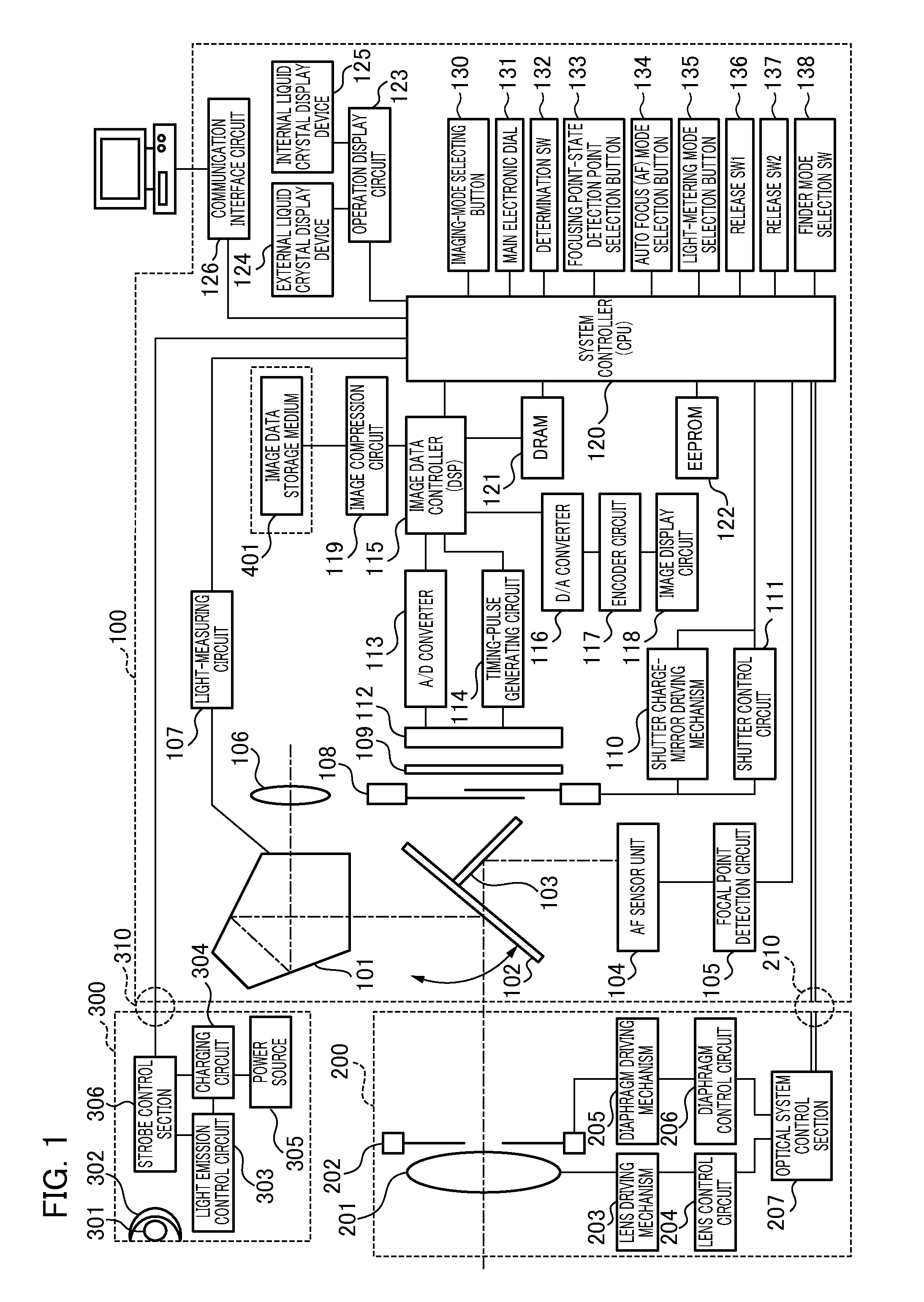
[0033]FIG. 1 is a block diagram illustrating an exemplary configuration of a single-lens reflex type digital camera as an imaging apparatus according to an embodiment. An imaging lens unit 200 is detachably mounted on a camera body 100 via a mounting mechanism (not shown). A mounting part includes a group of electric contact points 210. The group of contact points 210 transmits and receives a control signal, a state signal, a data signal, and the like between the camera body 100 and the imaging lens unit 200. The group of contact points 210 also supplies various types of voltages including a power supply voltage transmitted from the imaging lens unit 200 to a system controller 120. Owing to the group of contact points 210, the camera body 100 can communicate with the imaging lens unit 200 to drive an imaging lens 201 (while only one lens is sh...


PUM


Abstract

In an imaging apparatus including a stepping motor that drives a diaphragm, a favorable moving image exposure control is carried out while reducing electrical power required for holding the diaphragm position. For moving image exposure control, a determination unit determines the presence or absence of the diaphragm driving. When a rotor and the magnetic poles of the stator do not face to each other in the first operation mode, the control unit of a stepping motor drives the rotor to a facing position, and shuts off the current in a coil. When the diaphragm driving does not occur in the second operation mode, the control unit of a stepping motor shuts off the current in the coil at the state where the rotor of the motor and the magnetic poles of the stator face to each other. A holding current to be supplied to the motor is shut off in the first and second operation modes, whereby the lower power consumption can be realized. The program profile of a diaphragm drive method and an exposure control is switched depending on the type of an imaging lens unit, whereby a favorable moving image exposure control can be realized.

Description

BACKGROUND OF THE INVENTION[0001]1. Field of the Invention[0002]The present invention relates to a drive and position control of a diaphragm. In particular, the present invention relates to a technique in which power consumption can be lowered in consideration of responsiveness of moving image exposure.[0003]Description of the Related Art[0004]Currently, in what is referred to as a “single-lens reflex type” digital camera of which the interchangeable lens is removable, a product that has a live view function that displays a preview image prior to photographing a still picture on a TFT monitor disposed on the rear face of a casing or is capable of photographing a moving picture is known. Conventionally, there has been required high-speed responsiveness and high positional accuracy for focus driving, diaphragm driving, and the like of an interchangeable lens, since the primary aim was still picture photographing. For this reason, a stepping motor excellent in driving characteristics a...

Claims


Application Information

Patent Timeline
Patent Type & Authority Applications(United States)
IPC IPC(8): G03B9/02H04N5/225H04N5/235
CPCG03B7/08G03B7/26G03B19/12G03B9/02
Inventor HIROSE, MINORU
Owner CANON KK
Why Eureka
Try Eureka