Integrated boiler and air pollution control systems

a boiler and integrated technology, applied in the field of air pollution control, can solve the problems of significant problems in industrial settings with respect to both hot side and cold side scr installations, poor proven results of such techniques, and inability to use hot side scr processes in conjunction with wood-fired burners, etc., to reduce multiple pollutants, and reduce nox and oxidizing co

Inactive Publication Date: 2011-03-31
BABCOCK POWER ENVIRONMENTAL INC (US)
View PDF27 Cites 15 Cited by
  • Summary
  • Abstract
  • Description
  • Claims
  • Application Information

AI Technical Summary

Benefits of technology

In accordance with certain embodiments, the step of reducing at least one pollutant includes introducing flue gas into the emission treatment system at a temperature in a range of about 360° F. to about 500° F. and discharging emission treated flue gas from the emission treatment system at a temperature in a range of about 360° F. to about 500° F., wherein the emission treatment system includes a multi-pollutant catalytic reactor configured to reduce multiple pollutants from flue gas in the emission treatment system. The step of reducing at least one pollutant can include reducing NOX and oxidizing CO from a flue gas flow entering the multi-pollutant catalytic reactor at a temperature in a range of about 360° F. to about 500° F. The step of reducing at least one pollutant can include reducing NOX and oxidizing CO from a flue gas flow entering the multi-pollutant catalytic reactor at a temperature in a range of about 400° F. to about 450° F.
These and other features of the systems and methods of the subject invention will become more readily apparent to those skilled in the art from the following detailed

Problems solved by technology

However, in view of the generally poor proven results of such techniques (i.e., NOX removal efficiencies of 50% or less), recent attention has focused instead upon various flue gas denitrification processes (i.e., processes for removing nitrogen from flue gas prior to the flue gas being released into the atmosphere).
Unfortunately, significant problems are encountered in industrial settings with respect to both hot side and cold side SCR installations.
For example, hot side SCR processes are not optimal for use in conjunction with wood-fired burners.
This is because ash present within the wood contains alkalis, which can cause damage to the catalyst due to poisoning during the SCR process.
Cold side SCR processes avoid this disadvantage because the particulate matter is removed prior to reaching the catalyst, but are plagued by thermal inefficiency due to their reliance on indirect heat exchangers.
In addition to its low heat recovery, a conventional ‘tail-end’ SCR system requires significant additional fan power, typically a booster fan, to overcome pressure drop through the SCR catalyst and the recovery heat exchanger.

Method used


Image

  • Integrated boiler and air pollution control systems
  • Integrated boiler and air pollution control systems
  • Integrated boiler and air pollution control systems

Examples


Embodiment Construction

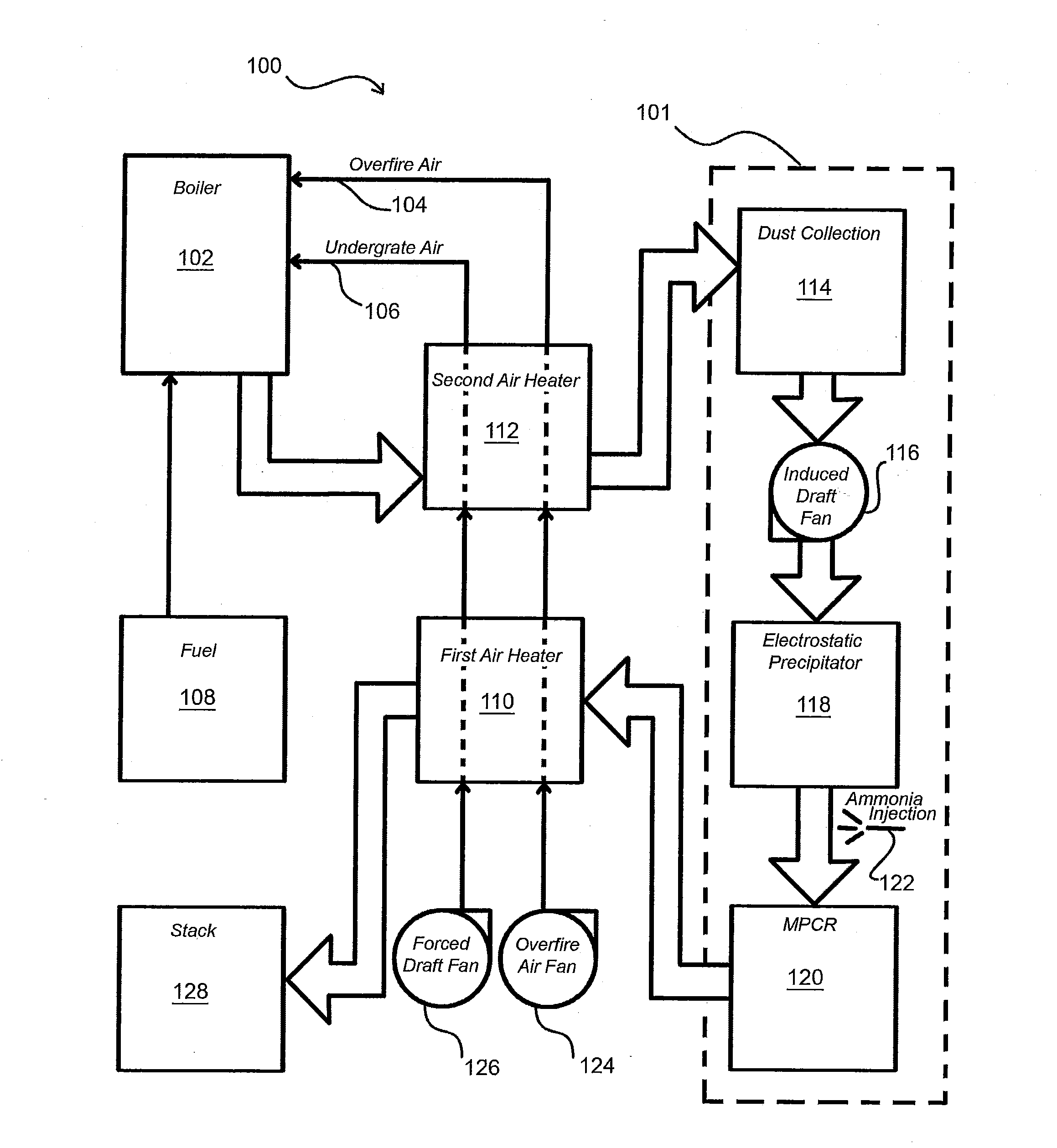
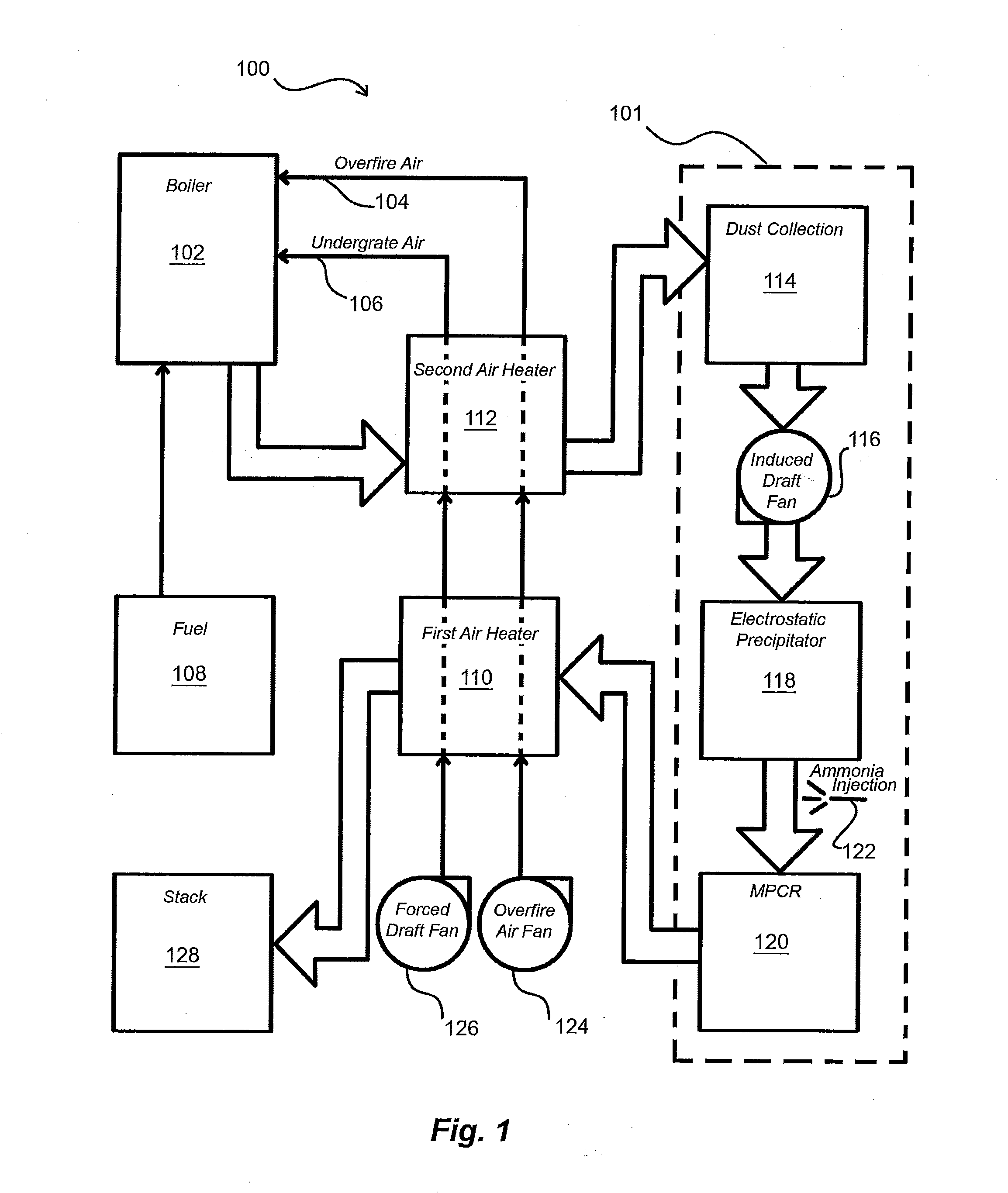
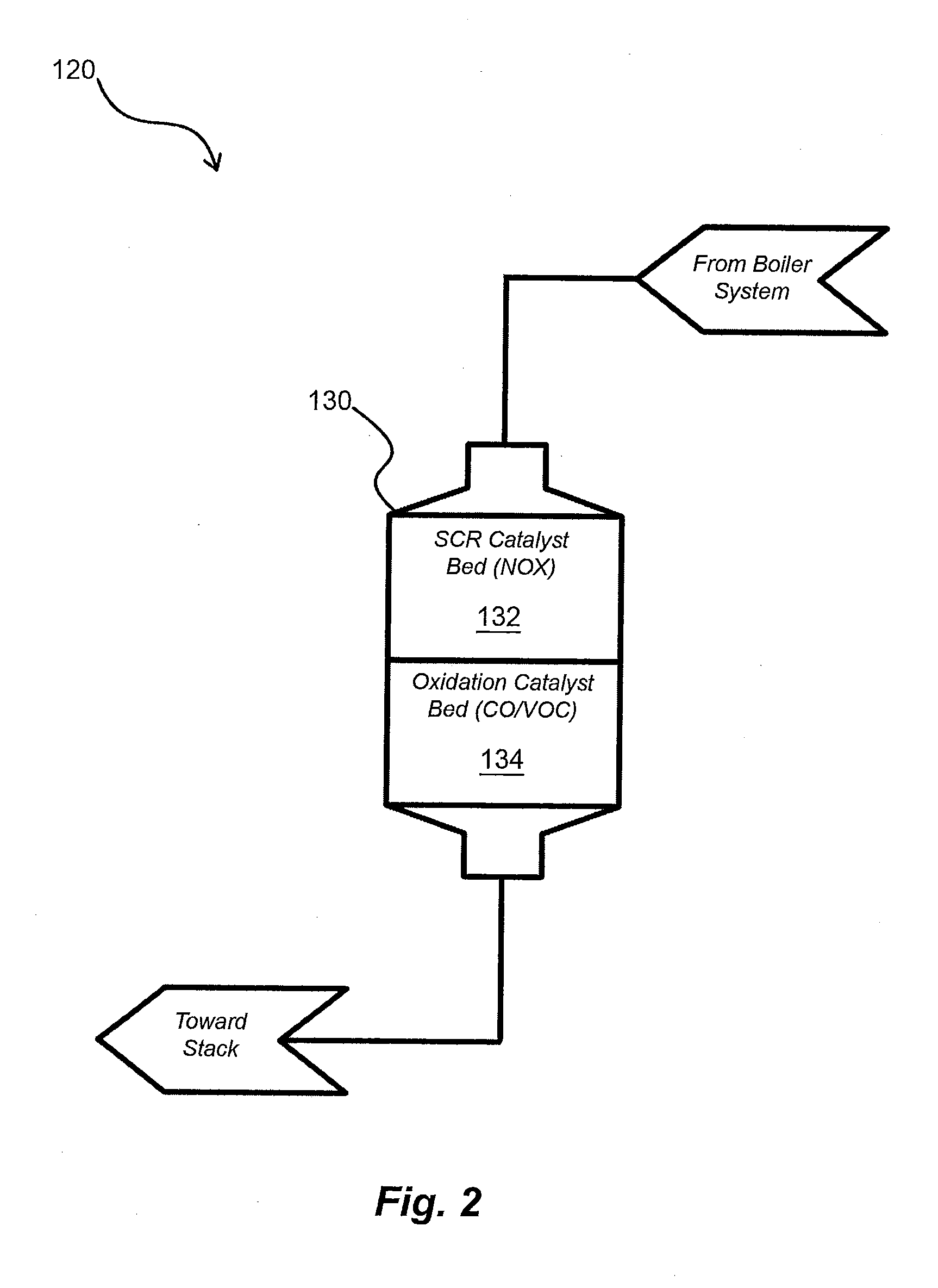
Reference will now be made to the drawings wherein like reference numerals identify similar structural features or aspects of the subject invention. For purposes of explanation and illustration, and not limitation, a partial view of an exemplary embodiment of the air pollution control system in accordance with the invention is shown in FIG. 1 and is designated generally by reference character 100. Other embodiments of air pollution control systems in accordance with the invention, or aspects thereof, are provided in FIG. 2, as will be described. The systems and methods of the invention can be used to reduce air pollution and increase thermal efficiency for power and / or heat plants fueled by biomass fuels and / or other fuels, for example.

Referring now to FIG. 1, system 100 includes a boiler 102, which can be a stoker such as a Riley Advanced Stoker™, available from Riley Power Inc. of Worcester, Mass., for example. The boiler could instead be a fluidized bed boiler, a bubbling fluidiz...


PUM

PropertyMeasurementUnit
temperatureaaaaaaaaaa

Abstract

An air pollution control system includes an emission treatment system configured to receive flue gas, to reduce at least one pollutant therefrom, and to output emission treated flue gas. A first air heater in fluid communication with the emission treatment system includes a heat exchanger for heating forced air introduced thereto above a base temperature and thereby cooling emission treated flue gas from the emission treatment system to a stack discharge temperature. A second air heater in fluid communication with the first air heater to receive heated forced air therefrom includes a heat exchanger for heating forced air introduced thereto to a preheat temperature for combustion in a boiler and thereby cooling flue gas introduced from a boiler to the second air heater to an emission treatment temperature. The second air heater is in fluid communication with the emission treatment system to introduce cooled flue gas thereto.

Description

BACKGROUND OF THE INVENTION1. Field of the InventionThe present invention relates to air pollution control, and more particularly, to treating flue gas to reduce pollutant emission therefrom.2. Description of Related ArtA variety of devices are known in the art for controlling pollution in exhaust and flue gas, for example, flue gas emitted from boilers. Among such devices, many are directed to reduction of NOX, CO, VOC, and the like, from flue gas prior to releasing the flue gas into the atmosphere. For years, a commonly employed technique for reducing NOX, CO, and VOC emissions was to modify the combustion process itself, e.g., by flue gas recirculation or the overfire air. However, in view of the generally poor proven results of such techniques (i.e., NOX removal efficiencies of 50% or less), recent attention has focused instead upon various flue gas denitrification processes (i.e., processes for removing nitrogen from flue gas prior to the flue gas being released into the atmosp...

Claims


Application Information

Patent Timeline
Patent Type & Authority Applications(United States)
IPC IPC(8): B01D53/56F01N3/10B01D50/00B01D53/34B01D53/62B01D53/72
CPCB01D53/8656B01D2251/2062B01D2255/1021B01D2255/1023B01D2257/404B01D2257/502Y02C20/10B01D2258/0283B03C9/00B03C11/00B03C2201/02F01N3/0814F01N3/2066B01D2257/708Y02A50/20
Inventor ABRAMS, RICHARD F.LEWIS, MARKPENTERSON, JEFFREY
Owner BABCOCK POWER ENVIRONMENTAL INC (US)
Why Eureka
Try Eureka