Air metering device for gas turbine engine

a gas turbine engine and air metering technology, which is applied in the direction of machines/engines, mechanical equipment, lighting and heating apparatus, etc., can solve the problems of affecting the ability to meter air, differing thermal growth,

Inactive Publication Date: 2011-04-07
PRATT & WHITNEY CANADA CORP
View PDF12 Cites 25 Cited by
  • Summary
  • Abstract
  • Description
  • Claims
  • Application Information

AI Technical Summary

Problems solved by technology

However, since components tend to be made from differing materials, depending on their particular design requirements, this results in differing thermal growths, which may be significant depending on the materials, location in the engine, etc.
The differing thermal expansion / contraction characteristics of various engine components can negatively affect the ability to meter air accurately, however, and hence the designer must optimize the gap size to, for example, provide a desired flow for a threshold or target operating segment of the aircraft cycle (e.g. cruise, take-off, etc.), and sub-optimal performance for other segments.

Method used


Image

  • Air metering device for gas turbine engine
  • Air metering device for gas turbine engine
  • Air metering device for gas turbine engine

Examples


Embodiment Construction

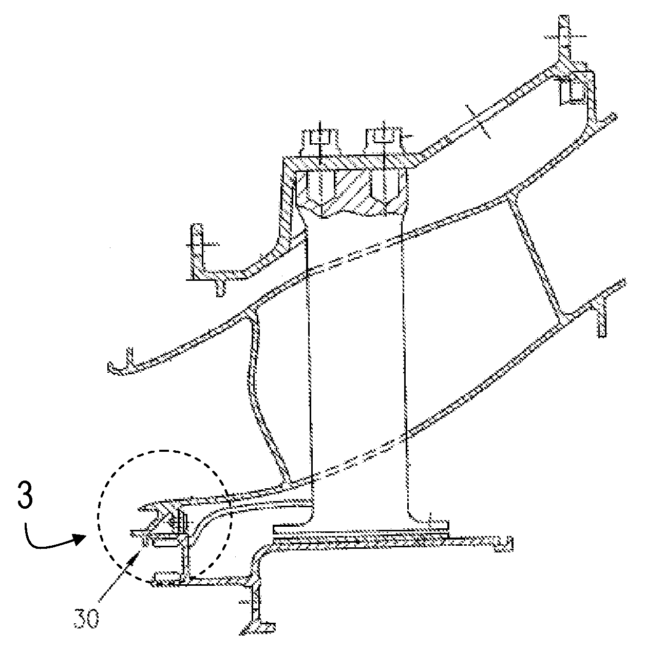
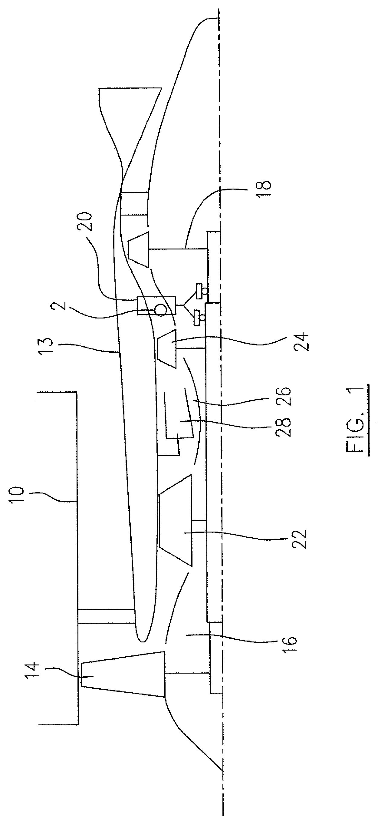
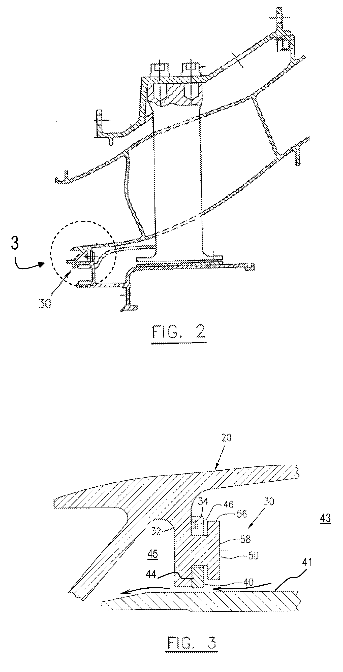
[0012]Referring to FIG. 1, a gas turbine engine presented as an example of the application of the described subject matter includes a housing or nacelle 10, a core casing 13, a low pressure spool assembly which includes a fan assembly 14, a low pressure compressor assembly 16 and a low pressure turbine assembly 18, and a high pressure spool assembly which includes a high pressure compressor assembly 22 and a high pressure turbine assembly 24. The core casing 13 surrounds the low and high pressure spool assemblies in order to define a main fluid path (not numbered) therethrough. In the main fluid path there is provided a combustor 28 to constitute a gas generator section 26. Generally, those downstream of the gas generator section 26 are hot sections and any engine structures in the hot sections such as a mid-turbine frame 20 which is located between the high pressure turbine assembly 24 and the low pressure turbine assembly 18. Referring to FIG. 2, a secondary air system (not indica...


PUM


Abstract

An air metering apparatus for a secondary air system of gas turbine engine includes a metering gap defined between surfaces comprised of one or more metals having one of similar coefficients of thermal expansion or similar thermal expansions at an operating temperature. Provided is an air metering gap which undergoes thermal growth in a way which provides a suitable air metering gap during engine running conditions.

Description

TECHNICAL FIELD[0001]The described subject matter relates generally to gas turbine engines and, more particularly, to an improved air metering for a gas turbine engine.BACKGROUND OF THE ART[0002]Gas turbine engines have secondary air systems which provide cooling to various engine parts. It is desirable to minimize cooling air requirements to improve engine efficiency, and hence secondary air is typically metered, such as through metering holes in an engine casing or similar structure. A simpler arrangement is sometime to meter air through gaps between adjacent parts in the secondary air system. However, since components tend to be made from differing materials, depending on their particular design requirements, this results in differing thermal growths, which may be significant depending on the materials, location in the engine, etc. The differing thermal expansion / contraction characteristics of various engine components can negatively affect the ability to meter air accurately, ho...

Claims


Application Information

Patent Timeline
Patent Type & Authority Applications(United States)
IPC IPC(8): F02C7/20
CPCF02C7/28F01D11/18
Inventor DUROCHER, ERICLEGARE, PIERRE-YVES
Owner PRATT & WHITNEY CANADA CORP
Why Eureka
Try Eureka