Refrigerating cycle device and air conditioner

a technology of refrigerating cycle and air conditioner, which is applied in the direction of refrigerating machines, lighting and heating apparatus, heating and refrigeration combinations, etc., can solve the problems of reducing the efficiency of the refrigerating cycle, and increasing the weight of the entire apparatus, so as to prevent deterioration, save energy, and ensure reliability

Inactive Publication Date: 2011-04-07
MITSUBISHI ELECTRIC CORP
View PDF12 Cites 19 Cited by
  • Summary
  • Abstract
  • Description
  • Claims
  • Application Information

AI Technical Summary

Benefits of technology

[0012]According to the refrigerating cycle device of the present invention, since the air adsorbing means is provided on the refrigerant circuit so as to adsorb an oxygen molecule and a nitrogen Molecule in the air of the refrigerant circuit, the oxygen molecule and the nitrogen molecule to become impurities can be prevented from circulating. Therefore, even if the HFO refrigerant or the like which has double bond and as chemically unstable is circulated through the refrigerant circuit, the HFO refrigerant and the air can be prevented from deteriorating or the like by chemical reaction or the like, performances of the refrigerating cycle device can be maintained for a long time, and moreover, reliability can be ensured. Also, since deterioration of the refrigerant can be prevented and feeding of a heat quantity can be maintained without applying a load on the compressor, energy can be saved. Since the HFO refrigerant such as tetrafluoropropylene used as a refrigerant at this time has a global warming coefficient equivalent to that of carbon dioxide, which is TO a natural refrigerant, for example, and is a so-called nonflon refrigerant, the refrigerant is suitable from a viewpoint of the environment.

Problems solved by technology

For example, carbon dioxide (CO2) has a considerably small global warming coefficient, but efficiency of the refrigerating cycle is lowered and power consumption is increased.
Also since pressure resistance of equipment, piping and the like needs to be raised in general as compared with a case using a refrigerant circulated in a refrigerant circuit (R410A refrigerant, for example), a weight of the entire apparatus is increased, which results in cost-up and prevents popularization.
Therefore, if impurities other than the refrigerant are present in the refrigerant circuit, the refrigerant reacts with the impurities and is deteriorated, which is a problem.
Also, a chemically reacted new substance further reacts with refrigerant oil, which generates sludge or blocks a thin, pipe such as a capillary tube or an expansion valve, which is a problem.

Method used


Image

  • Refrigerating cycle device and air conditioner
  • Refrigerating cycle device and air conditioner
  • Refrigerating cycle device and air conditioner

Examples


embodiment 1

[0021]An embodiment of the present invention will be described below referring to the attached drawings.

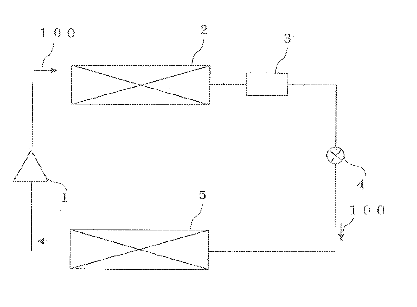
[0022]FIG. 1 is a diagram illustrating a basic configuration of a refrigerating cycle device according to Embodiment 1 of the present invention. Arrows 100 in FIG. 1 indicate a direction along which a refrigerant flows. In FIG. 1, the refrigerating cycle device has a compressor 1, a condenser 2, air adsorbing means 3, a throttle device (expansion valve) 4, and an evaporator 5. Each device (element part) is connected to each other by piping so as to constitute a refrigerant circuit, in the refrigerant circuit, a refrigerant, to be circulated is sealed. As the refrigerant, in this Embodiment, a refrigerant having a double bond in an atomic bond such as CF3CH ═CF2, CF3CF ═CF2 including an HFO refrigerant containing tetrafluoropropene (represented by CF3CF═CH2: 2,3,3,3-Tetrafluoropropene, HFO-1234yf) is sealed.

[0023]The compressor 1 sucks the refrigerant to be circulated through the r...

embodiment 2

[0042]FIG. 5 is a diagram illustrating a configuration of a refrigerating cycle device according to Embodiment 2 of the present invention. In FIG. 5, means and the like given the same symbols as those in FIG. 1 and toe like will be described sup that the operations and the like described in Embodiment 1 are performed. Air separating / removing means 11 is means for separating the refrigerant and air using a density difference between the liquid refrigerant and air. Thus, the air separating / removing means 11 needs to be installed where the refrigerant is in the liquid state. Thus, in FIG. 5, the air separating / removing means 11 is installed in a high-pressure liquid line between the condenser 2 and the throttle device 4. Here, in each diagram which will be described in this Embodiment, it is supposed that the upper side is an upward direction in the vertical direction, and the lower side is a downward direction in the vertical direction.

[0043]FIG. 6 is a diagram illustrating a section ...

embodiment 3

[0056]In the above Embodiments, the cases in which the air adsorbing means 3 and the air separating / removing means 11 are installed singularly in the refrigerant circuit (refrigerating cycle device) were shown, but the number of installation is not limited to one. Particularly, the air separating / removing means 11 may be provided at plural spots where air can be easily collected.


PUM


Abstract

A compressor 1 for compressing a refrigerant containing a hydrofluoroolefin refrigerant, a condenser 2 for condensing the refrigerant by heat exchange, a throttle device 4 for decompressing the condensed refrigerant, an evaporator 5 for evaporating the refrigerant by heat exchange between the decompressed refrigerant and air, and air adsorbing means 3 for adsorbing oxygen and nitrogen are connected by piping so as to configure a refrigerant circuit through which the refrigerant containing the hydrofluoroolefin refrigerant is circulated.

Description

TECHNICAL FIELD[0001]The present invention relates to a refrigerating cycle device such as an air conditioner, a water heater and the like. Particularly, reliability of a refrigerating cycle device is improved by providing removing means for removing substances that react with an unstable refrigerant.BACKGROUND ART[0002]In general, in a refrigerating cycle device using a refrigerating cycle (heat-pump cycle) such as an air conditioner, a freezer, a water heater and the like, basically, a compressor, a condenser (heat exchanger), an expansion valve, and an evaporator (heat exchanger) are connected by piping so as to constitute a refrigerant circuit through which a filled refrigerant is circulated. The refrigerant compressed an the compressor becomes a high-temperature and high-pressure gas refrigerant and is fed into the condenser. The refrigerant having been fed into the condenser is liquefied by emitting neat through heat exchange with a heat-exchange target. The liquefied refriger...

Claims


Application Information

Patent Timeline
Patent Type & Authority Applications(United States)
IPC IPC(8): F25B43/00F25B1/00F25B29/00
CPCF25B43/043F25B43/003F25B2500/01
Inventor MORIMOTO, HIROYUKIOKADA, KAZUKISAIKUSA, TETSUJI
Owner MITSUBISHI ELECTRIC CORP
Why Eureka
Try Eureka