Device and method for generating a beam of acoustic energy from a borehole, and applications thereof

a technology of acoustic energy and a beam, which is applied in the field of generating acoustic energy beams from boreholes, can solve the problems of limited output of downhole acoustic transducers, difficult to generate collimated acoustic beam signals, and limited acoustic interrogation of subsurface features, etc., to achieve the effect of improving the beam collimation

Active Publication Date: 2011-04-07
TRIAD NAT SECURITY LLC +1
View PDF62 Cites 21 Cited by
  • Summary
  • Abstract
  • Description
  • Claims
  • Application Information

AI Technical Summary

Benefits of technology

The device can further include a first acoustic lens or lens assembly arranged along a propagation path of the acoustic beam, configured to alter a beam geometry of the acoustic beam to control the beam collimation and / or a second acoustic lens or lens assembly arranged to compensate for an alteration of the beam radiation pattern due to a geometry of the interface and acoustic property differences between the borehole and the material surrounding the borehole. Further, the first acoustic lens assembly can be a converging lens to improve the beam collimation and the second acoustic lens assembly can be a diverging lens, wherein the diverging lens can be arranged to compensate for the effect on the propagating beam of a cylindrical borehole-formation interface.

Problems solved by technology

Acoustic interrogation of subsurface features tends to be limited by the size and power of practical sources, and in practice, the output of downhole acoustic transducers is limited by the power transmission capabilities of the wire line cable.
It is difficult to generate a collimated acoustic beam signal in the 10 kHz-100 kHz range from the borehole to probe the rock formation surrounding a borehole, or any other material in the environment, such as casing or cement, with conventional low-frequency transducers.
In the borehole environment, these conditions are not often achievable because of underlying physics constraints, engineering feasibility or operating conditions.

Method used


Image

  • Device and method for generating a beam of acoustic energy from a borehole, and applications thereof
  • Device and method for generating a beam of acoustic energy from a borehole, and applications thereof
  • Device and method for generating a beam of acoustic energy from a borehole, and applications thereof

Examples


Embodiment Construction

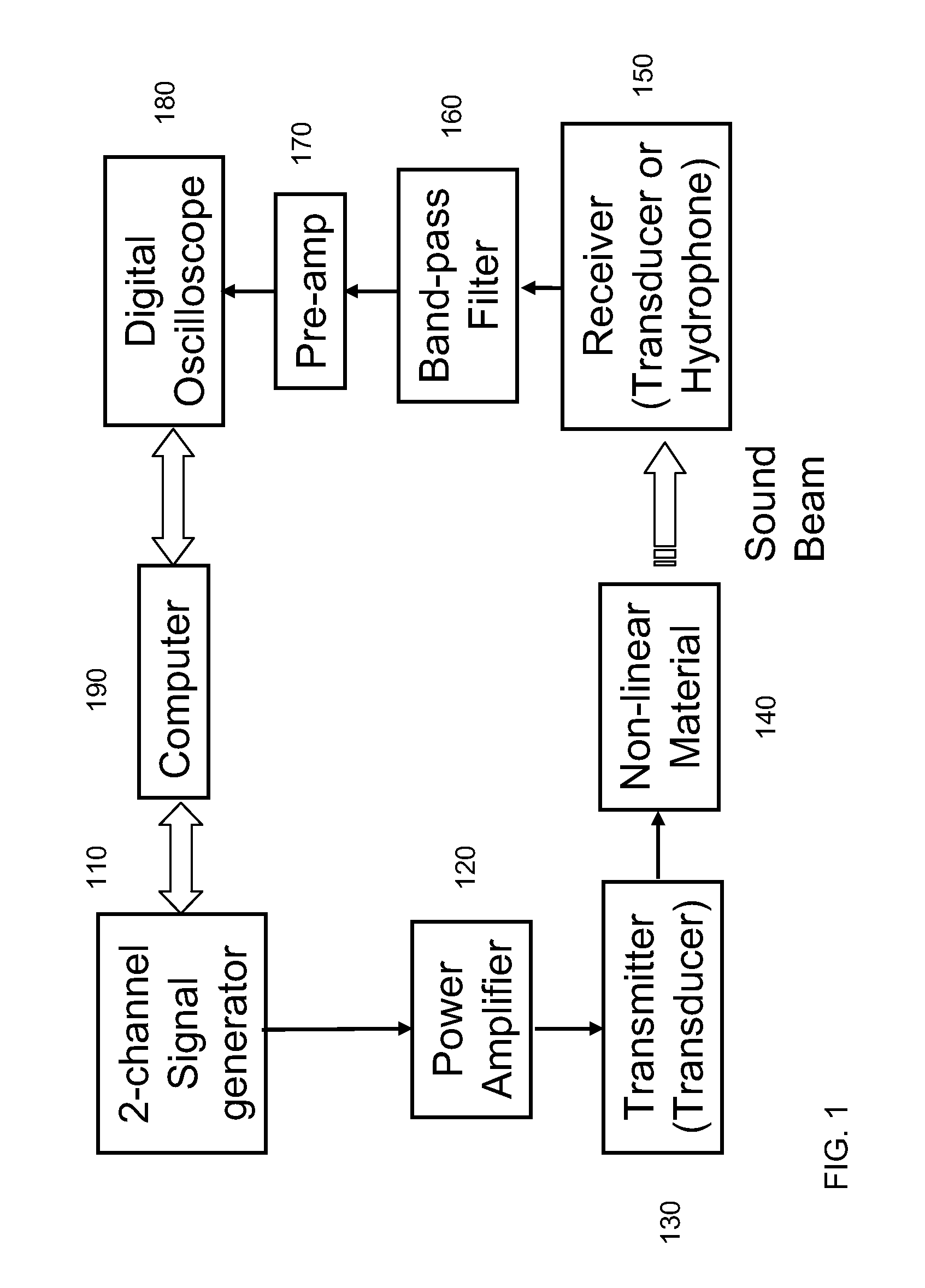
FIG. 1 shows a generalized diagram of the device for producing the collimated beam in accordance with an aspect of the invention. In some embodiments, one or more sources 110 are used to produce a first signal at a first frequency and a second signal at a second frequency. By way of a non-limiting example, the signals can be produced by a 2-channel signal generator. Similar signal or function generators may be used. The signals from the sources are received by one or more signal amplifiers 120 and are transmitted to one or more transducers 130 that are used to generate acoustic waves at the first and the second frequencies. The first and second frequencies can be broadband having a frequency range including a central frequency with some frequency spread about the central frequency. Piezoelectric transducers are one type suitable for this application. If more than one transducer is use, they can be arranged in an array configuration. By way of non-limiting examples, the array configu...


PUM


Abstract

In some aspects of the invention, a method of generating a beam of acoustic energy in a borehole is disclosed. The method includes generating a first broad-band acoustic pulse at a first broad-band frequency range having a first central frequency and a first bandwidth spread; generating a second broad-band acoustic pulse at a second broad-band frequency range different than the first frequency range having a second central frequency and a second bandwidth spread, wherein the first acoustic pulse and second acoustic pulse are generated by at least one transducer arranged on a tool located within the borehole; and transmitting the first and the second broad-band acoustic pulses into an acoustically non-linear medium, wherein the composition of the non-linear medium produces a collimated pulse by a non-linear mixing of the first and second acoustic pulses, wherein the collimated pulse has a frequency equal to the difference in frequencies between the first central frequency and the second central frequency and a bandwidth spread equal to the sum of the first bandwidth spread and the second bandwidth spread.

Description

FIELDThe present invention relates generally to acoustic interrogation of rock formations around a borehole and more particularly to using the combination of an acoustic source including a single transducer or an array of transducers in the wellbore coupled to a non-linear material for producing an acoustic beam as a probing tool from a borehole to interrogate the properties of rock formations and materials surrounding the borehole.BACKGROUNDAcoustic interrogation of subsurface features tends to be limited by the size and power of practical sources, and in practice, the output of downhole acoustic transducers is limited by the power transmission capabilities of the wire line cable. High frequency signals have a relatively short penetration distance, while low frequency signals generally require large sources, clamped to the borehole wall, to maximize energy transfer to the formation and minimize unwanted signals within the well bore. It is difficult to generate a collimated acoustic...

Claims


Application Information

Patent Timeline
Patent Type & Authority Applications(United States)
IPC IPC(8): G01V1/48
CPCG01V1/46
Inventor VU, CUNG KHACSINHA, DIPEN N.PANTEA, CRISTIANNIHEI, KURT T.SCHMITT, DENIS P.SKELT, CHRISTOPHER
Owner TRIAD NAT SECURITY LLC
Why Eureka
Try Eureka