Self-ligating bracket with universal application

a self-ligating, universal technology, applied in the field of orthodontic brackets, can solve the problems of large time-consuming and laborious archwire installation, large area of food particles likely to be trapped in the archwire, and the small size of the ligature or ligating module, so as to reduce the size of the bracket, and reduce the irritation

Inactive Publication Date: 2011-04-07
MASHOUF CAMERON
View PDF24 Cites 41 Cited by
  • Summary
  • Abstract
  • Description
  • Claims
  • Application Information

AI Technical Summary

Benefits of technology

[0039]Another significant advantage of the present invention is its compact design. Presently available self-ligating brackets inherently consist of multiple parts whereas conventional brackets are manufactured as monolithic structures. Because self-ligating brackets have complex structures associated with multiple parts, and because self-ligating brackets embody additional features to support the capability of self-ligatibility, they are inherently more bulky and generally extent further in one or more of their dimensions. From the patient's point of view, larger or more prominent brackets are undesirable both for aesthetic reasons of being more visible and due to greater irritation they can cause to the insides of the cheeks and lips. The present invention allows for reduction in the size of the bracket to any degree without compromising the self-ligating mechanical integrity of the bracket.
[0040]A further advantage of the simple, open design of the present invention is that it does not afford an opportunity for the accumulation of tartar that can interfere with the self-ligation mechanism. As noted previously, tartar accumulation, particularly in self-ligating brackets using a slide mechanism, can often have an adverse effect on the orthodontist's ability to manipulate the ligation mechanism as well as the patient's comfort.

Problems solved by technology

Round archwires used early in treatment are not considered as being true edgewise wires because being round in cross-section; they are incapable of imparting tortional forces against the flat slot walls and floor.
The small size of the ligatures or ligating modules requires substantial time for installation of the archwire.
Hygiene is another problem since the use of ligatures or ligating modules increases the areas that food particles are likely to be trapped.
This increases the incidence of enamel discoloration and decalcification during treatment.
Friction presents a separate problem since traditional bracket systems rely on the ligatures or ligating modules to hold the archwire within the slot of the bracket.
This binding or “bungee-cord effect” creates friction during orthodontic tooth movement and consequently increases the force needed for sliding movement particularly during the early “leveling and alignment” phase of treatment.
The additional force required to move the teeth creates additional discomfort for patients and increases the time for completion of treatment.
However, most of these brackets have complex designs, incorporating features requiring prohibitively expensive machining operations or comprising multiple separate parts, which in turn increases the bulkiness of the brackets, clogging of the moving parts and ultimately the chances of failure.
Further, they include multiple parts which make them prone to failure and require complex and costly manufacturing processes.
In the case of self-ligating brackets that employ a sliding mechanism, a common problem is the accumulation of tarter in the guiding grooves that hold the clip and allow the clip to slide between the open and closed position.
In such circumstances, the self-ligating clip gets stuck in the closed position requiring use of tarter solvents and / or excessive manual pressure to open a stuck ligation slide.
Clogging-up of the slide mechanism can be a source of considerable anxiety, pain and discomfort for the patient.
Another disadvantage of the existing sliding and rotary self-ligating brackets is that the entire front surface of the bracket is covered by the self-ligation mechanism blocking the arch-wire slot and the tie wings and making them inaccessible to conventional elastic or steel tie.
The archwire which is not secured in the depth of the slot does not fully express the built-in tip and torque of the bracket.
The inherent inability of the existing self-ligating brackets to take full advantage of the built-in tip and torque becomes a problem in the finishing stages of orthodontic treatment.
Because self-ligating brackets have complex structures associated with multiple parts, and because self-ligating brackets embody additional features to support the capability of self-ligatibility, they are inherently more bulky and generally extent further in one or more of their dimensions.
From the patient's point of view, larger or more prominent brackets are undesirable both for aesthetic reasons of being more visible and due to greater irritation they can cause to the insides of the cheeks and lips.
As noted previously, tartar accumulation, particularly in self-ligating brackets using a slide mechanism, can often have an adverse effect on the orthodontist's ability to manipulate the ligation mechanism as well as the patient's comfort.

Method used


Image

  • Self-ligating bracket with universal application
  • Self-ligating bracket with universal application
  • Self-ligating bracket with universal application

Examples


Embodiment Construction

[0041]Details of the illustrated orthodontic bracket are intended to be interpreted as being merely illustrative and are not to be taken as being restrictive of the practical combinations of such features within the scope of this disclosure and the claims which follow.
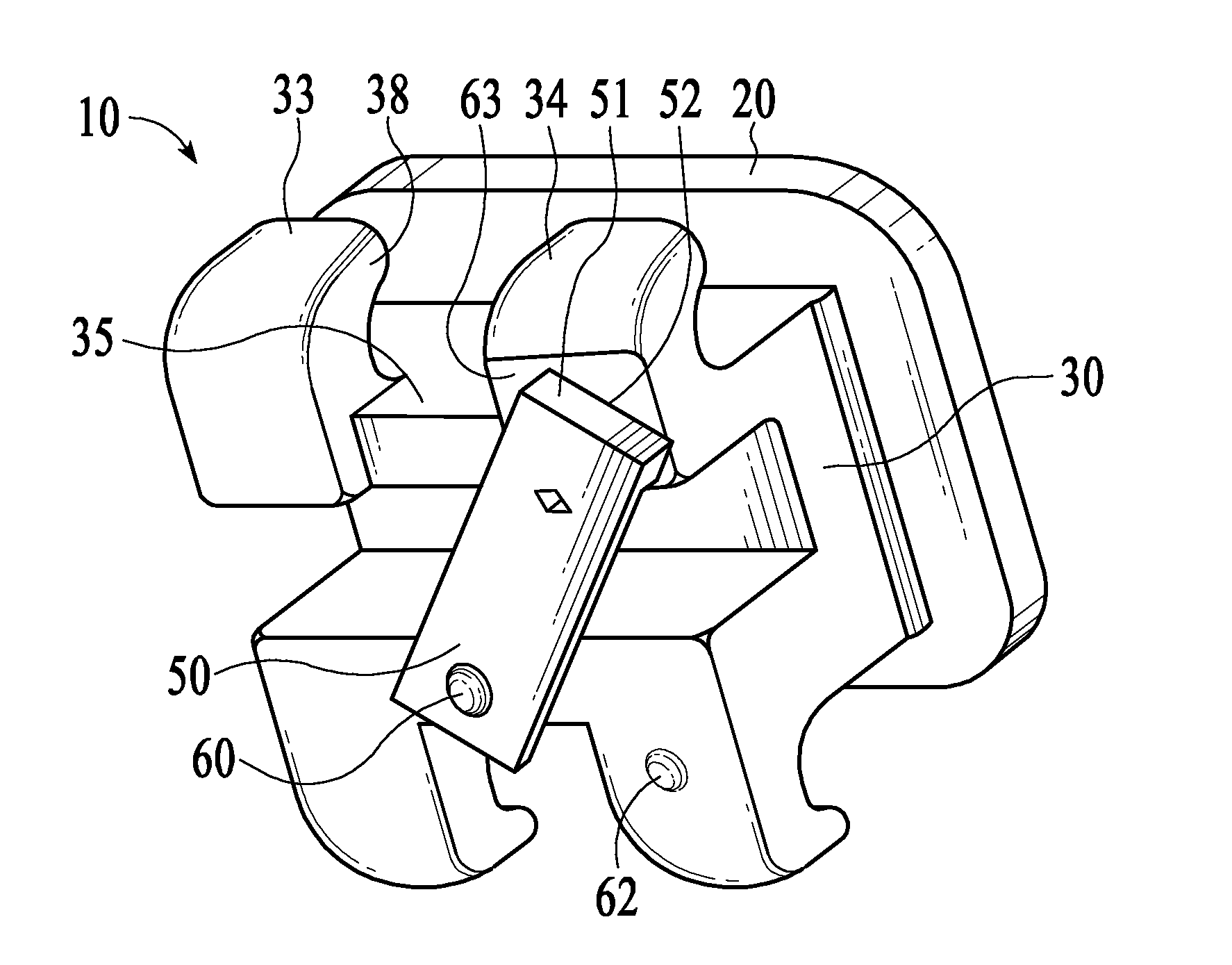
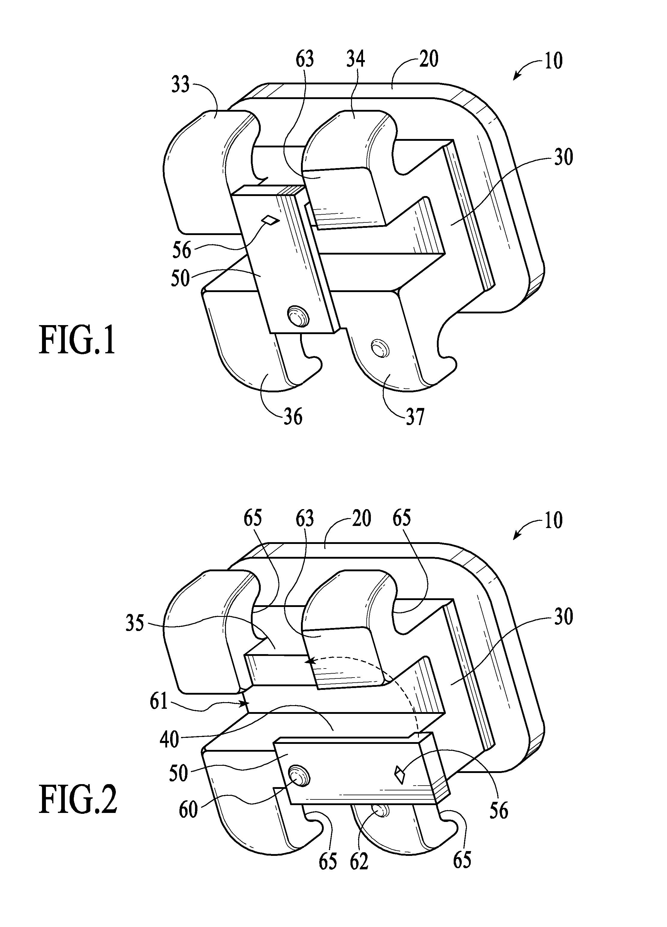
Orientation

[0042]The following terms are used in this description to facilitate interpretation of the illustrations.

[0043]An anterior surface is directed buccally in relation to the supported tooth. A posterior surface is directed lingually in relation to the supported tooth.

[0044]Superior is toward the occlusal plane. Inferior is toward the gingival plane. Transverse is parallel to the occlusal plane. Upright is parallel to the gingival-occlusal plane. Height is the bracket dimension between the gingival and occlusal planes.

[0045]A leading edge is the mesially directed side surface of the bracket assembly. A trailing edge is the distally directed side surface of the bracket assembly.

[0046]FIGS. 1 and 2 are perspective...


PUM


Abstract

A compact orthodontic bracket that employs a simple method of self-ligation, is compatible with both permanent and deciduous teeth and is less expensive to manufacture than existing commercial brackets. The bracket utilizes a rotary plate that covers an arch wire slot when closed and can be pivotably opened to allow arch wire changes. Ligation may also be augmented using conventional ligatures on the paired tie wings. The simplicity of the ligating mechanism allows manufacturing of a smaller bracket. It is also less vulnerable to the clogging effects of salivary deposits than commercial self-ligating brackets currently in use.

Description

FIELD OF INVENTION[0001]This invention broadly relates generally to the field of orthodontic brackets. More specifically, the present invention discloses a self-ligating orthodontic bracket suitable for use on both permanent and deciduous teeth.BRIEF DESCRIPTION OF THE DRAWINGS[0002]FIG. 1 is a perspective view of the bracket assembly in closed position[0003]FIG. 2 is a perspective view of the bracket assembly in open position[0004]FIG. 3 is an anterior view of the bracket assembly showing the plane of movement of the rotary plate[0005]FIG. 3A is a side view of the rotary plate showing functional areas[0006]FIG. 4 is a superior view of the bracket assembly in intermediate position[0007]FIG. 5 is a perspective view of the bracket assembly in intermediate position[0008]FIG. 6 is a superior view of the bracket assembly in closed position[0009]FIG. 7 is a sectional view showing the relation of the rotary plate to the bracket assembly body[0010]FIG. 8 is a exploded view showing the relat...

Claims


Application Information

Patent Timeline
Patent Type & Authority Applications(United States)
IPC IPC(8): A61C7/24
CPCA61C7/285A61C7/14
Inventor MASHOUF, CAMERON
Owner MASHOUF CAMERON
Why Eureka
Try Eureka