Rotatable fixing member, manufacturing method thereof and fixing device

a technology of fixing member and manufacturing method, which is applied in the direction of electrographic process, coating, instruments, etc., can solve the problems of insufficient heat resistivity and durability, inability to obtain sufficient smoothness, and conventionally very difficult to form on the elastic, so as to prevent mud cracks, impair bonding properties, and cracks easily occur

Inactive Publication Date: 2011-04-07
CANON KK
View PDF13 Cites 23 Cited by
  • Summary
  • Abstract
  • Description
  • Claims
  • Application Information

AI Technical Summary

Benefits of technology

[0086]In general, the fluorocarbon polymer primer does not contain a binder component, for the purpose of preventing the mud crack during the drying and the baking, in a large amount. This is because when the amount of the binder component is large, an amount of a substance which is vaporized during the baking is increased and trapped by the parting layer on the primer layer and therefore the binder component adversely affects the film-forming property and impairs the bonding property. The fluorocarbon polymer primer dispersion which does not contain the binder component in the large amount is liable to cause the mud crack curing the drying. Particularly, when the dispersion is coated uniformly on the elastic member so as to effect leveling in a so-called wet state (in which the dispersion is not dried soon on the elastic member), the crack occurs easily during the drying. When the parting layer 2C in a state in which the mud cracks occur during the drying (FIG. 4(a)) is coated (FIG. 4(b)) and then baked, as schematically illustrated in FIG. 4(c), the cracks are enlarged by the influence of expansion of the base material 2A and the elastic layer 2B during the baking, so that the parting layer surface is largely roughened. As a coating method for preventing the occurrence of the mud crack during the drying, a general dry coating in spray coating, i.e., a method in which paint particles of the fluorocarbon polymer primer dispersion to be blown with a spray are made small to facilitate drying thereof after being deposited on the elastic layer surface may be used. Further, it is also possible to use a method in which the elastic member is heated and the fluorocarbon polymer dispersion is applied so that the paint particles are dried immediately after being deposited on the elastic member and thus small paint particles (FIG. 3(c)) are laminated. However, in general, in the spray coating method, the paint particles can be made small abut cannot be formed in a size of less than 1 μm, so that as shown in FIGS. 3(b) and 3(c), the paint particles have an outer size of 5 μm to several tens of microns and a thickness of about 2 μm already after the paint particles are deposited and dried on the surface of the elastic layer 2B. FIG. 3(b) is the SEM photograph showing a state of the primer layer formed by the dry coating (a state in which the paint particles are fixed and laminated without being leveled. FIG. 3(c) is the SEM photograph showing the state of the primer layer formed by the dry coating (enlarged fixed paint particles). The primer layer laminated on the elastic layer 2B by being repeatedly coated on the elastic layer 2B so as to cover at least the entire surface area of the elastic layer 2B has a final thickness of 4-6 μm (FIG. 5(a)). Further, the surface state thereof is, as shown in FIG. 3(b), such a roughened state that a large amount of the surface unevenness is present due to the shape of the fixed paint particles. In the case where the primer layer has the surface unevenness as described above, the surface of the parting layer 2C on the primer layer 2D is influenced by the surface unevenness of the primer layer, thus being liable to have an uneven surface (FIG. 5(b)).
[0087]As described above, there are the case where the parting layer surface is disturbed by progression of the crack in the primer layer during the baking and the case where the surface of the unbaked parting layer (the parting layer after the drying) is not smooth due to the surface unevenness of the primer layer. In these cases, in order to obtain good surface property and gloss, the fluorocarbon polymer for the parting layer is baked at a higher temperature or for a longer time. As a result, the fluorocarbon polymer is sufficiently melted and leveled and thus the parting layer surface is required to be smoothened. However, in this case, it is considerably feared that the underlying elastic layer is thermally deteriorated.
[0088]On the other hand, in the present invention, when the primer layer 2D itself has a very smooth surface and is thin (FIG. 6(a)), the unbaked parting layer surface itself (after the drying) has already been very smooth and good in property (FIG. 6(b)). Further, the primer layer 2D is very thin and does not readily cause the crack, so that the crack is also not readily generated in the parting layer itself during the baking and therefore the parting layer surface is not largely disturbed during the baking. Therefore, it is possible to obtain a ve

Problems solved by technology

However, the non-crystalline fluorocarbon polymer is liable to be softened, so that heat resistivity and durability cannot be sufficiently obtained.
However, in the case where this method is employed, the state of the primer layer is liable to disturb the smoothness of the surface of the fluorocarbon polymer, so that it is very difficult to obtain sufficient smoothness.
It has been conventionally very difficult to form on the elastic layer the fluorocarbon polymer parting layer, which

Method used


Image

  • Rotatable fixing member, manufacturing method thereof and fixing device
  • Rotatable fixing member, manufacturing method thereof and fixing device
  • Rotatable fixing member, manufacturing method thereof and fixing device

Examples


embodiment 1

(7) Examples of Embodiment 1

[0091]Specific examples of the fixing film 2 which is the rotatable fixing member in Embodiment 1 will be described.

(7-1) Fixing Film Manufacturing Method in Examples 1 to 3

[0092]The fixing films in Examples 1 to 3 have the same constitution except for their thicknesses.

(7-1-1) Preparation of Elastic Layer for Fixing Film

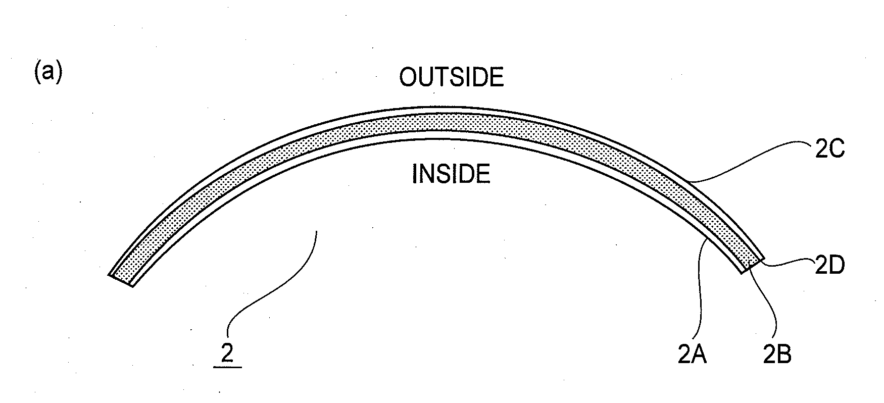
[0093]As the base material 2A, an SUS metal belt (flexible endless belt member) having a length of 240 mm, a thickness of 40 μm and an outer diameter of 30 mm was used. On an outer circumferential surface of the base material 2A2B, a high heat-resistant silicone rubber (“SE4400”, mfd. by Dow Corning Toray Co., Ltd.) which contained a heat-conductive filler in advance and had thermal conductivity of about 1 W / m·k was used. This silicone rubber was coated on the primer application area (300 μm in thickness and 230 mm in length) on the base material 2A by the ring coating method (FIG. 2(b)) to form a film and then the film was subjected to p...

embodiment 2

(2) Fixing Device 115

[0107]FIG. 7(a) is a schematic cross-sectional view of a principal part of a fixing device 115 in Embodiment 2. This fixing device 115 is of a so-called surface heating type fixing device and as the fixing roller for the fixing device of this type, the rotatable fixing member according to the present invention can be used. Referring to FIG. 7(a), a fixing roller 11 is the rotatable fixing member according to the present invention. An elastic pressing roller 12 is disposed below and in parallel to the fixing roller 11 and is pressed against the fixing roller 11 with a predetermined urging force by an unshown urging member. As a result, a fixing nip N2 with a predetermined width is created between the fixing roller 11 and the pressing roller 12. A heating unit 13 for externally heating the fixing roller 11 is disposed above and in parallel to the fixing roller 11. The heating unit 13 performs the function of applying heat from a ceramic heater 14 to the fixing rol...


PUM

PropertyMeasurementUnit
Thicknessaaaaaaaaaa
Thicknessaaaaaaaaaa
Thicknessaaaaaaaaaa

Abstract

A rotatable fixing member includes an elastic layer, a primer layer provided on the elastic layer, and a parting layer provided on the primer layer. The primer layer contains a crystalline fluorocarbon polymer having a functional group and has a thickness of 850 nm or less. The parting layer is a coating layer of a crystalline fluorocarbon polymer.

Description

FIELD OF THE INVENTION AND RELATED ART[0001]The present invention relates to a rotatable fixing member for use in an image forming apparatus such as a copying machine or a printer, a manufacturing method of the rotatable fixing member, and a fixing device. Here, the fixing device heats a recording material carrying thereon an image under application of heat and pressure. As such a fixing device, it is possible to use a fixing device for fixing or temporarily fixing an unfixed toner image on the recording material by heating the unfixed toner image, a glossiness (gloss) increasing device for increasing glossiness of the image by heating the image fixed on the recording material, a device for drying the recording material, on which the image has been formed by an ink jet method, by heating the recording material, and the like. Further, the rotatable fixing member includes, on a heat-resistant base material, at least an elastic layer, a primer layer of a fluorocarbon polymer (fluorine-...

Claims


Application Information

Patent Timeline
IPC IPC(8): C08F259/00G03G15/20B05D3/02
CPCG03G15/2053G03G2215/2035G03G15/206G03G15/2089G03G2215/2048
Inventor OMATA, MASAHITOUMEHARA, SHOJITETSUNO, SHUICHIASAKA, AKESHIONUMA, MASAYUKIBABA, YUSUKEKISHINO, KAZUO
Owner CANON KK
Why Eureka
Try Eureka