Explosion protection for a turbine and combustion engine

a technology of combustion engine and turbine, which is applied in the direction of engine components, gas turbine plants, and steam turbines, can solve the problems of insufficient cover-up of only a limited angular area, and achieve the effects of ensuring the protection of the whole and lasting area, improving the rupture strength, and improving the overall and lasting protection

Active Publication Date: 2011-04-14
ROLLS ROYCE SOLUTIONS GMBH
View PDF33 Cites 16 Cited by
  • Summary
  • Abstract
  • Description
  • Claims
  • Application Information

AI Technical Summary

Benefits of technology

to provide an explosion protection and a gas turbine as well as an internal combustion engine wherein, in case of an explosion of a turbine, an overall and lasting protection is ensured. In p

Problems solved by technology

Furthermore, the inventors determined that, for a protection from damages caused by

Method used


Image

  • Explosion protection for a turbine and combustion engine
  • Explosion protection for a turbine and combustion engine

Examples


Embodiment Construction

Below, identical or functionally identical parts are indicated by the same reference numerals.

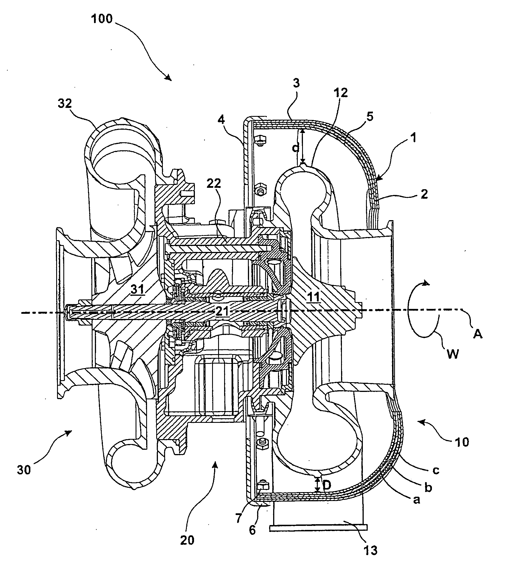
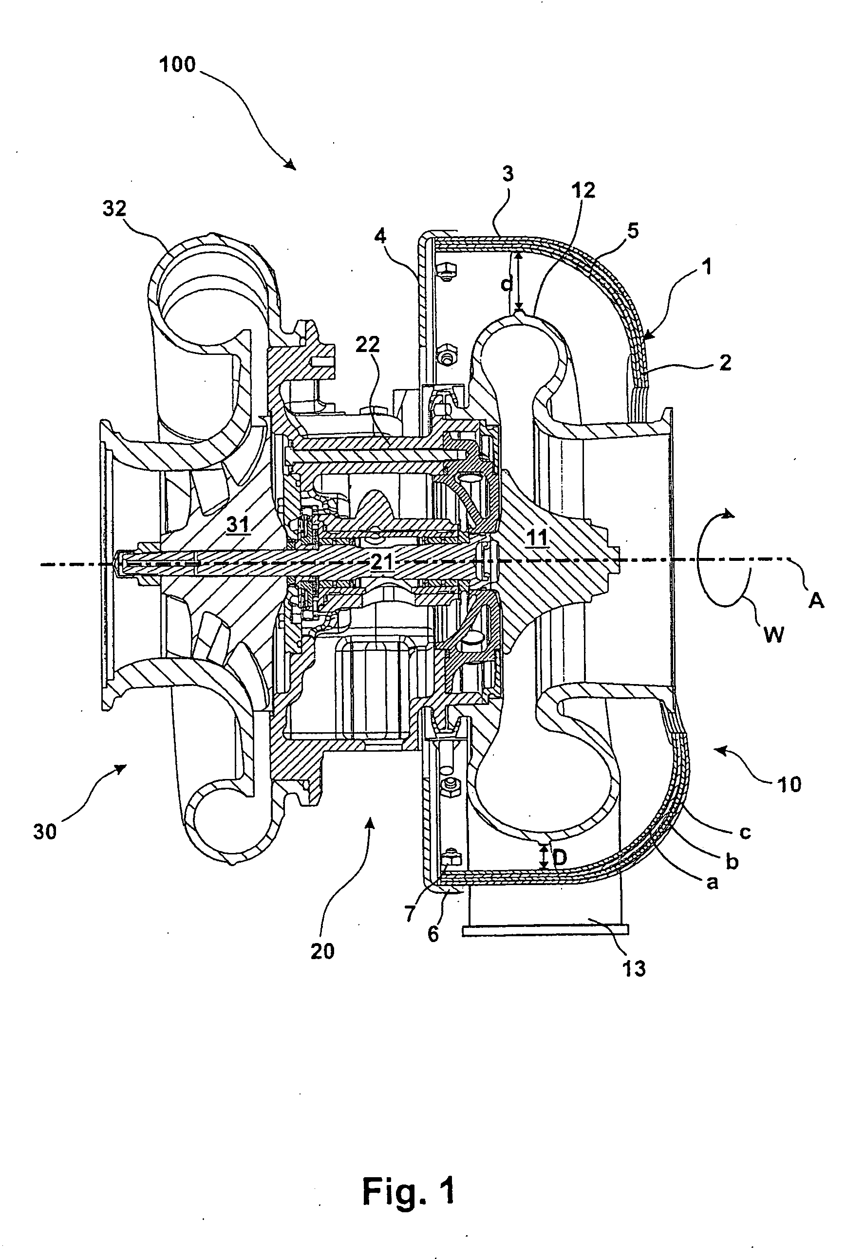
The exhaust gas turbocharger 100 as shown in FIG. 1 includes a gas turbine 10 provided with an explosion protection structure 1, a bearing 20 and a compressor 30. The turbine 10 includes a turbine wheel 11 which is mounted on a shaft 21 supported in a bearing 20 together with a compressor wheel 31 of the compressor 30. The compressor wheel 31 is arranged in a compressor housing 32, which in accordance with the design of the compressor as radial compressor, is a radial compressor housing to which fresh air is admitted in an axial direction.

The turbine wheel 11 of the turbine 10 is arranged in a turbine housing 12 in the form of a radial turbine housing. Exhaust gas of an internal combustion engine which is not shown in the FIGURE enters the housing 12 radially and leaves the housing along the axis A of the turbine.

For the unlikely case that—for example by entry of a foreign material or anoth...


PUM


Abstract

In an explosion protection for gas a turbine which includes a turbine wheel and a turbine housing surrounding the turbine wheel, wherein the explosion protection comprises a multi-layer structure of material of a high rupture strength, the explosion protection is in the form of an essentially closed pot including a bottom section and a sash extending fully around the bottom section for accommodating the turbine housing.

Description

BACKGROUND OF THE INVENTIONThe invention resides in an explosion protection for a gas turbo machine which includes a turbine housing completely enclosing a turbine wheel, wherein the explosion protection comprises a structure of several layers of a material with high rupturing strength. The invention also resides in a gas turbo machine with a turbine housing which fully surrounds a turbine wheel rotatably supported in the housing and which is provided with explosion protection. The invention is also concerned with a combustion engine and a gas turbo machine.Modern high-power gas turbo machines, for example exhaust gas turbochargers of internal combustion engines often present a risky to the ambient area in case of failure of their rotating parts. In particular, in uses where persons may be in close proximity of such machines, it must be ensured that, upon failure of such a machine, all fragments and, if applicable, secondary fragment parts are completely and safely captured.For exam...

Claims


Application Information

Patent Timeline
IPC IPC(8): F02C6/12F01D21/00
CPCF01D9/026F01D21/045F02C6/12F02B37/00F02B39/16F01D25/26
Inventor STROPH, PETERHEGNER, RONALD
Owner ROLLS ROYCE SOLUTIONS GMBH
Why Eureka
Try Eureka