
Vibration wave output instrument and method of using the same

a vibration wave and output instrument technology, applied in the direction of instruments, furniture, specific gravity measurement, etc., can solve the problems of difficult stably handling of the operator and the position of the vibration tool at the target region, and achieve the effect of enhancing the accuracy of the vibration device, stable and convenient handling, and shortening the distance of the vibration wave movemen

Active Publication Date: 2011-04-14
QUANTA COMPUTER INC
View PDF7 Cites 0 Cited by
  • Summary
  • Abstract
  • Description
  • Claims
  • Application Information

AI Technical Summary

Benefits of technology

The present patent is about a vibration wave output instrument that can be used to test the reaction of a human body to vibration waves. The instrument includes a base, a vibration device, a pressing device, and a position mechanism. The vibration device sends vibration waves to a target region, while the pressing device keeps pressing on the region. The position mechanism carries both the pressing device and the vibration device to the target region. The instrument also includes a mark on the target region, a step of moving the vibration device to aim at the mark, and a step of extending a pneumatic telescopic shaft to push the vibration device, so that the vibration rod of the vibration device touches the mark and outputs vibration waves to the mark. The instrument provides a stable and convenient way to handle the vibration device and enhances the accuracy of testing.

Problems solved by technology

However, because the skin surfaces of the target region are irregularly unplaned, and the vibration tool is provided with a certain weight, an operator is hard to stably handle and position the vibration tool at the target region precisely if the vibration tool is provided without an effective and easy means for tightly fixing the vibration tool on the target region thereof.

Method used


Image

  • Vibration wave output instrument and method of using the same
  • Vibration wave output instrument and method of using the same
  • Vibration wave output instrument and method of using the same

Examples


Embodiment Construction

[0018]In the following detailed description, for purposes of explanation, numerous specific details are set forth in order to provide a thorough understanding of the disclosed embodiments. It will be apparent, however; that one or more embodiments may be practiced without these specific details. In other instances, well-known structures and devices are schematically shown in order to simplify the drawings.

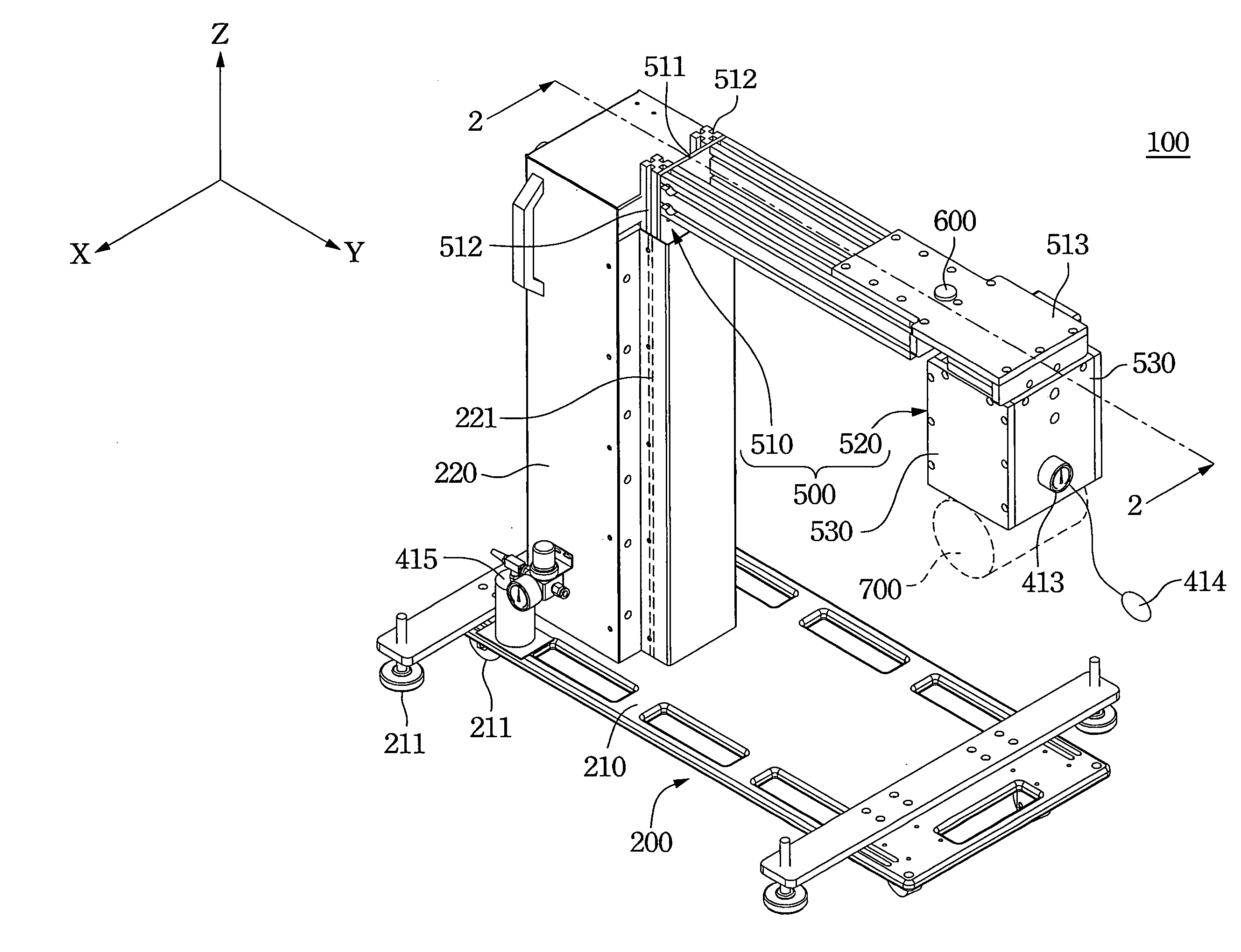
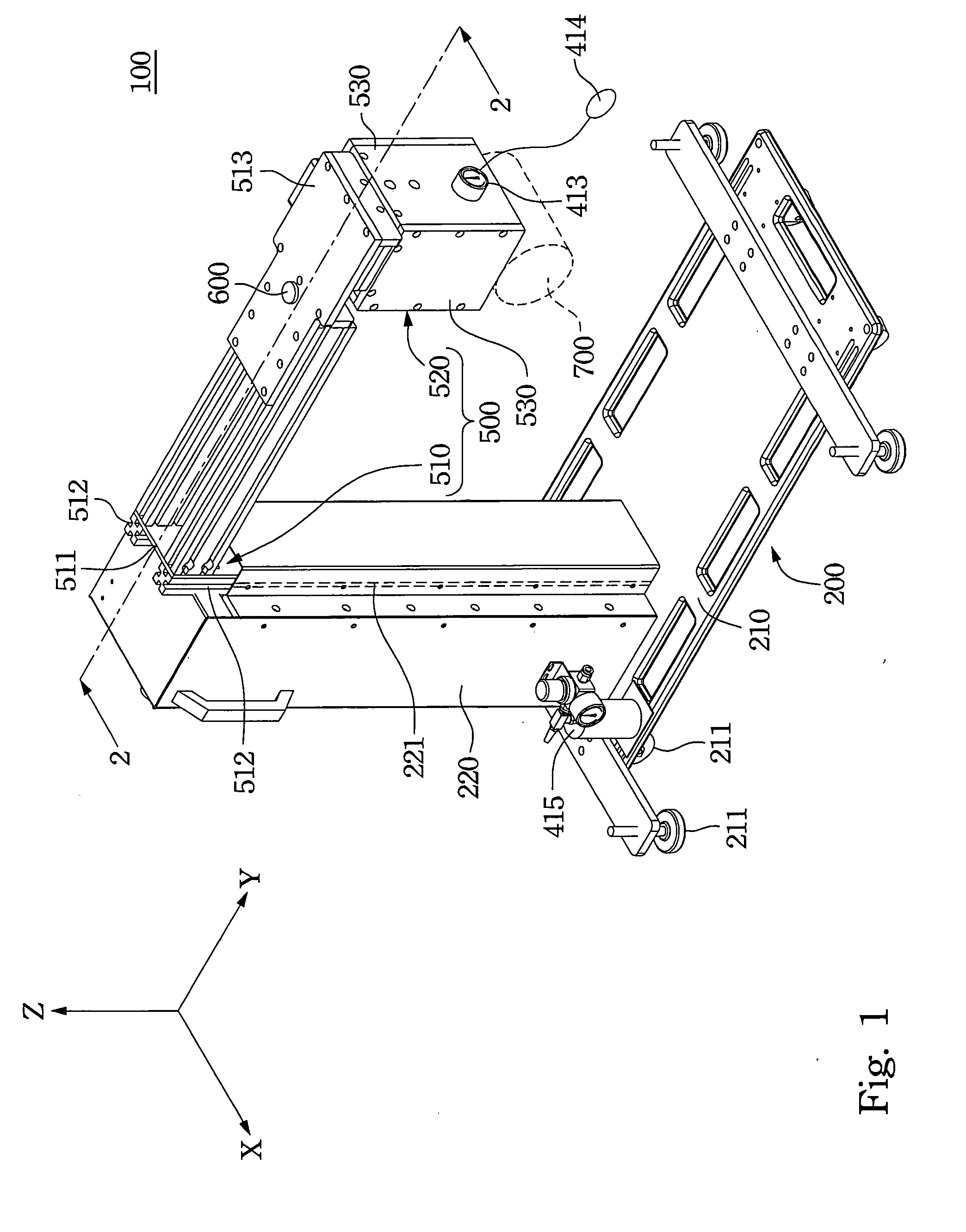
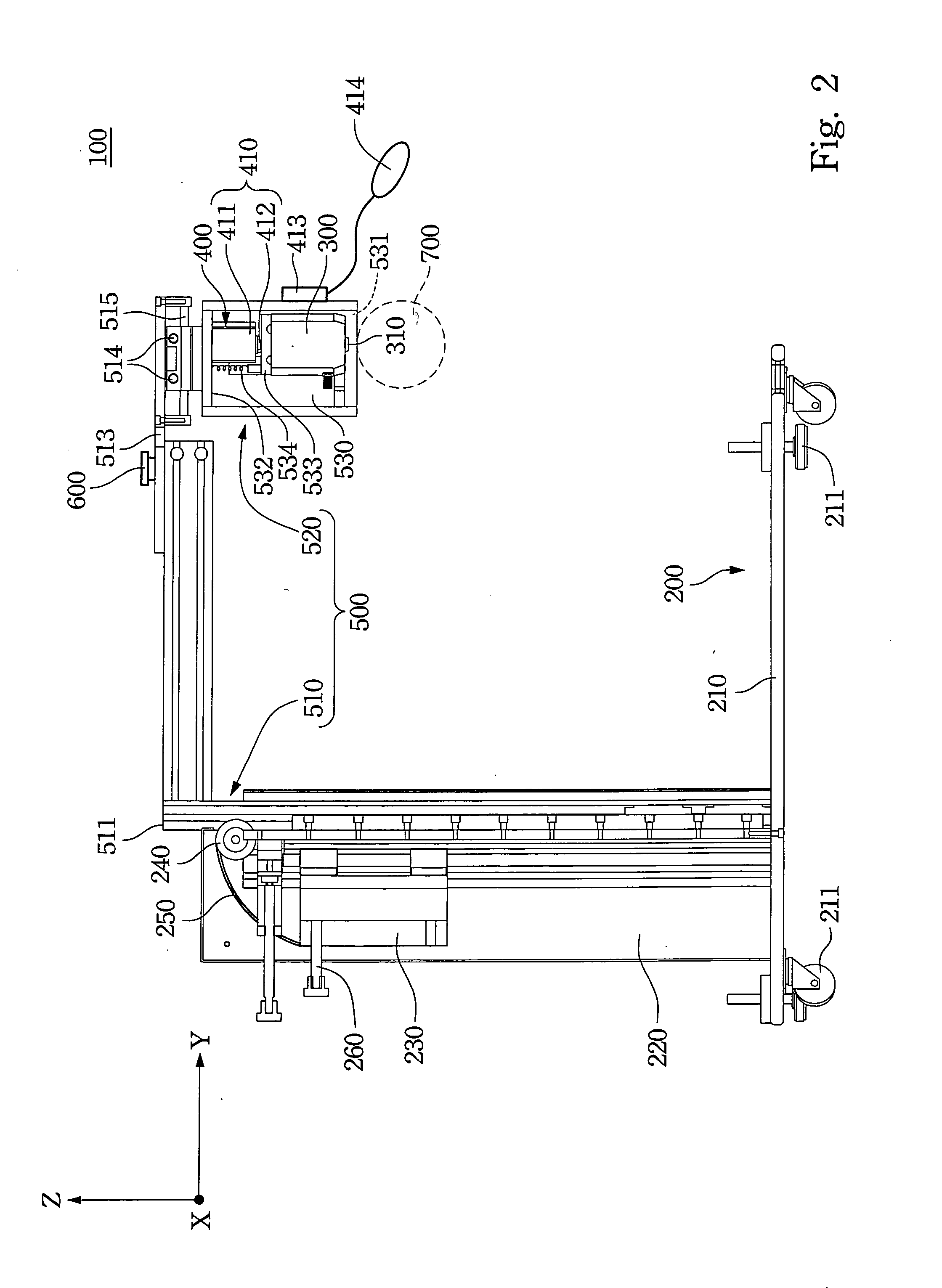
[0019]Refer to FIG. 1 and FIG. 2 in which FIG. 1 is a three dimensional view of a vibration wave output instrument in accordance with one embodiment of the present disclosure, and FIG. 2 is a cross-sectional view along a line 2-2 in FIG. 1 of the vibration wave output instrument.

[0020]A vibration wave output instrument 100 provided in the disclosure at least has a base 200, a vibration device 300, a pressing device 400 (also called as a pre-press unit, see FIG. 2) and a position mechanism 500.

[0021]The vibration device 300 has a vibration rod 310 provided at one end thereof. When t...


PUM

PropertyMeasurementUnit
elasticaaaaaaaaaa
bone mineral densityaaaaaaaaaa
weightaaaaaaaaaa

Abstract

A vibration wave output instrument and its use method are provided. The vibration wave output instrument has a base, a vibration device, a pressure device, and a position mechanism. The position mechanism brings both the vibration device and the pressure device to a target region. The pressure device pushes the vibration device to touch against the target region. The vibration device outputs vibration waves beneath the target region.

Description

RELATED APPLICATIONS[0001]This application claims priority to Taiwan Application Serial Number 98134161, filed Oct. 8, 2009, which is herein incorporated by reference.BACKGROUND[0002]1. Technical Field[0003]The disclosure relates to a signal output device, more particularly to a vibration wave output instrument and a method of using the same.[0004]2. Description of Related Art[0005]When elderly people suffer from Osteoporosis or Osteoarthritis syndrome, ache that occurs from Osteoporosis or Osteoarthritis syndrome tortures the elderly people a lot. In order to get information of people's human bone mineral density, and to diagnose the condition of people's hip joint (e.g. slack or loose), one of the methods is to send some vibration waves into a human body from a signal output source of a vibration tool (vibrator) through a target region (e.g. limbs) of the human body. When the vibration waves move in the human body and hit the tested bones, some reflective waves will be generated f...

Claims


Application Information

Patent Timeline
Patent Type & Authority Applications(United States)
IPC IPC(8): G01N29/04G01V1/155
CPCA61B5/0051A61B5/4528A61B5/4509A61B5/064
Inventor WU, YU-MINYANG, CHIN-WENYU, CHIH-HSIUNGLIN, HSIAO-CHENGWU, HSIN-HSUEH
Owner QUANTA COMPUTER INC
Learn More