
Apparatus, System, and Method for Reductant Line Heating Control

a technology of reductant and heating control, applied in mechanical equipment, machines/engines, transportation and packaging, etc., can solve the problems of increasing the risk of overheating the reductant, increasing the energy, software and hardware costs, and increasing the bulk and complexity of the system

Active Publication Date: 2011-04-14
CUMMINS INTPROP INC
View PDF22 Cites 29 Cited by
  • Summary
  • Abstract
  • Description
  • Claims
  • Application Information

AI Technical Summary

Benefits of technology

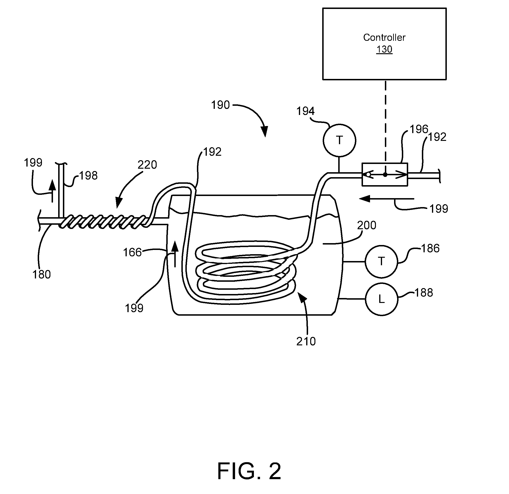
According to one implementation of the apparatus, the reductant tank outlet coolant temperature target is defined by a predetermined upper temperature threshold and a predetermined lower temperature threshold. In yet another implementation of the apparatus, the reductant tank outlet coolant temperature target comprises a coolant temperature value sufficient to thaw reductant in the reductant tank during operation of the internal combustion engine, prevent refreezing of the reductant in the reductant tank during operation of the internal combustion engine, and maintain a temperature of reductant in the reductant tank and reductant delivery line below a maximum tolerable temperature during operation of the internal combustion engine.

Problems solved by technology

Electrical heaters, however, suffer from several limitations.
For example, due to the difficulties in measuring the temperature of reductant inside a reductant line, electrical heaters require an ambient air temperature sensor as the primary input for proper operation.
Unfortunately, ambient air temperature sensors may be defective or become inaccurate over time based on limits and locations of ambient air temperature sensors, which may lead to an increased risk of overheating the reductant.
In addition to an ambient air temperature sensor, electrical heaters require a separate controller, battery, and control relay, each of which may add to the energy, software, and hardware costs, as well as the bulk and complexity of the system.
The controls used in conventional coolant-based reductant heating systems do not control or modulate the coolant flow rate.
Further, due to the absence of a temperature sensor in the reductant line, another limitation of conventional systems is the inability to ensure the temperature of reductant in a reductant line is maintained above the freezing point of the reductant and below an upper threshold corresponding with the maximum temperature allowed in the reductant delivery system.

Method used


Image

  • Apparatus, System, and Method for Reductant Line Heating Control
  • Apparatus, System, and Method for Reductant Line Heating Control
  • Apparatus, System, and Method for Reductant Line Heating Control

Examples


Embodiment Construction

Reference throughout this specification to “one embodiment,”“an embodiment,” or similar language means that a particular feature, structure, or characteristic described in connection with the embodiment is included in at least one embodiment of the present disclosure. Appearances of the phrases “in one embodiment,”“in an embodiment,” and similar language throughout this specification may, but do not necessarily, all refer to the same embodiment. Similarly, the use of the term “implementation” means an implementation having a particular feature, structure, or characteristic described in connection with one or more embodiments of the present disclosure, however, absent an express correlation to indicate otherwise, an implementation may be associated with one or more embodiments.

In the following description, numerous specific details are provided to impart a thorough understanding of embodiments of the disclosure. One skilled in the relevant art will recognize, however, that the disclo...


PUM


Abstract

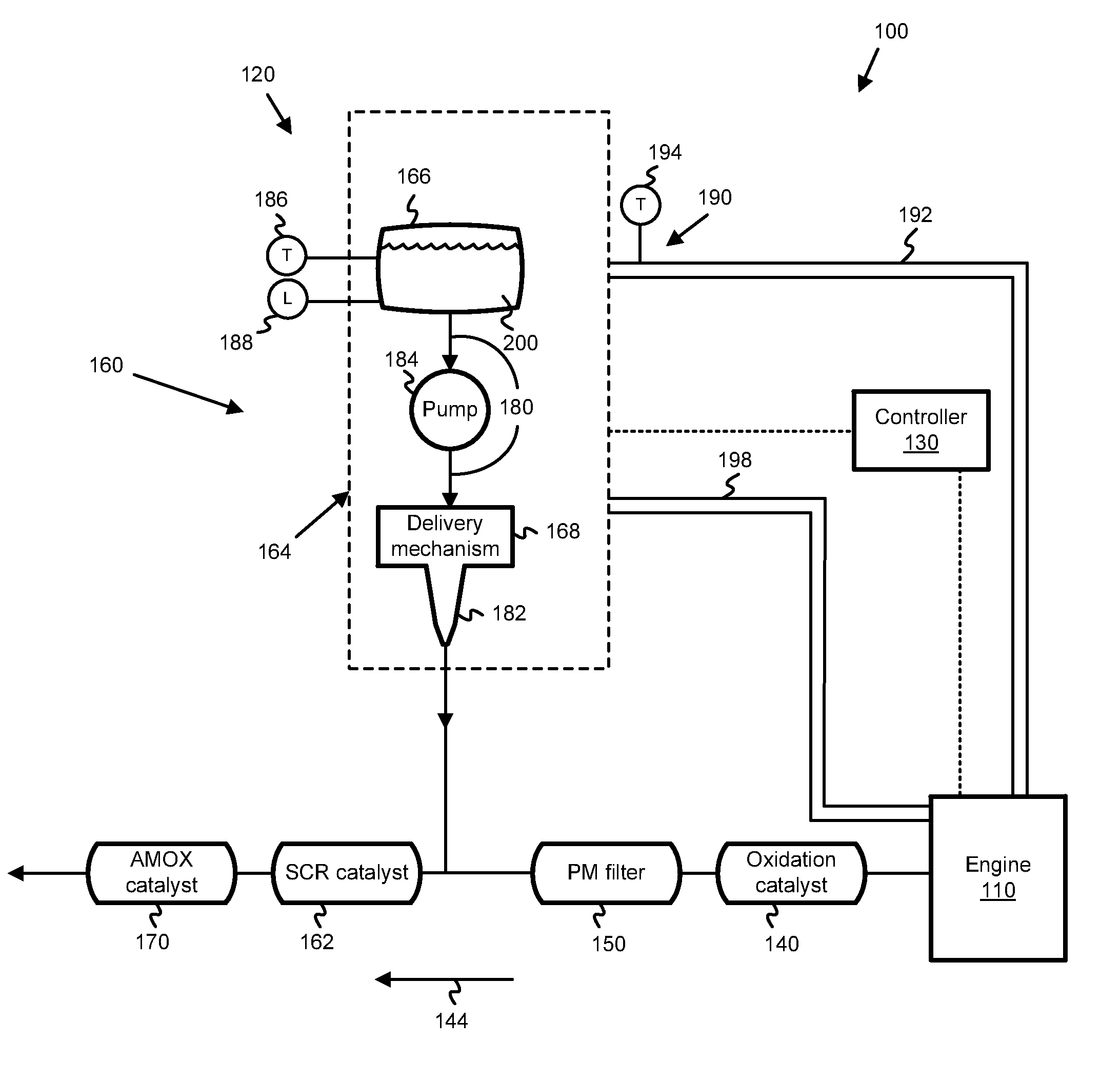
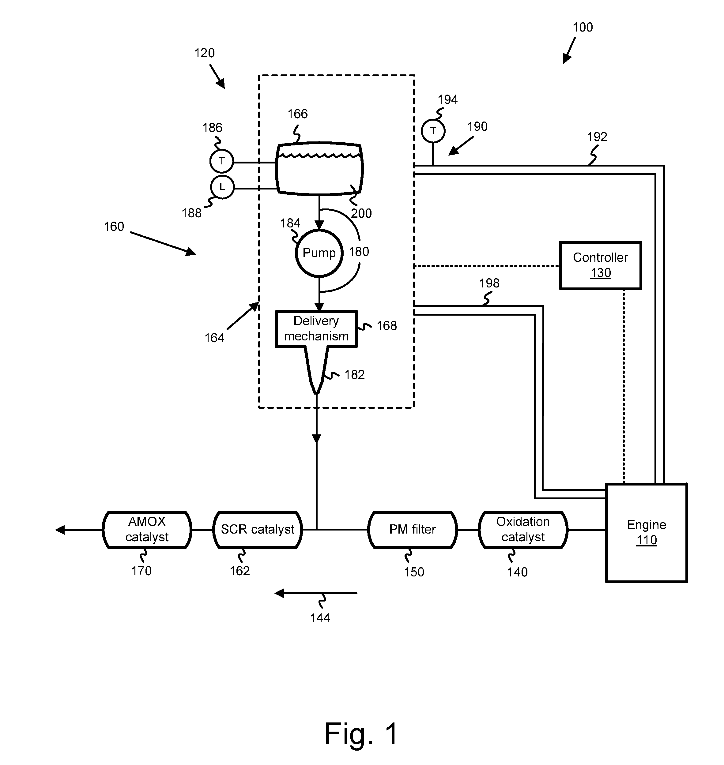
In one embodiment, an apparatus is disclosed for heating a reductant delivery line using coolant from an internal combustion engine where the reductant delivery line receives reductant from a reductant tank and a portion of a coolant line is positioned within the reductant tank. The apparatus includes a coolant temperature module that is configured to determine a reductant tank outlet coolant temperature target. Additionally, the apparatus includes a coolant flow rate module that is configured to generate a coolant valve flow rate command and transmit the command to a coolant valve. The coolant valve is controllable to regulate the flow rate of coolant through the coolant line. The coolant valve flow rate command is based on the reductant tank outlet coolant temperature target, a reductant tank inlet coolant temperature, and a reductant tank reductant temperature.

Description

FIELDThis invention relates to selective catalytic reduction (SCR) systems for internal combustion engines, and more particularly to controlling the temperature of a reductant used by SCR systems to reduce NOx emissions in exhaust gas.BACKGROUNDExhaust after-treatment systems receive and treat exhaust gas generated from an internal combustion engine. Typical exhaust after-treatment systems include various components configured to reduce the level of harmful exhaust emissions present in the exhaust gas. For example, some exhaust after-treatment systems for diesel powered internal combustion engines include various components, such as a diesel oxidation catalyst (DOC), particulate matter filter or diesel particulate filter (DPF), and an SCR catalyst. In some exhaust after-treatment systems, exhaust gas first passes through the diesel oxidation catalyst, then passes through the diesel particulate filter, and subsequently passes through the SCR catalyst.Each of the DOC, DPF, and SCR cat...

Claims


Application Information

Patent Timeline
IPC IPC(8): F01P7/00B60H1/03
CPCF01N3/208F01N2610/02F01N2610/10F01N2610/1406Y02T10/24F01N2900/1814F01N2610/1486F01N2900/0412F01N2900/08F01N2900/1811F01N2610/105Y02A50/20Y02T10/12
Inventor OGUNLEYE, HAKEEMQI, BAOHUAMCDANIEL, MICKEY
Owner CUMMINS INTPROP INC
Learn More