Retrodirective transmit and receive radio frequency system based on pseudorandom modulated waveforms

a radio frequency system and pseudo-random modulation technology, applied in the direction of antennas, antenna details, electrical equipment, etc., can solve the problems of van atta array not addressing the integration of retrodirective arrays, van atta arrays were somewhat impractical for communications, 80s saw very little advancement in the technology or application of retrodirective antennas in rf systems, etc., to improve the detection of very small objects and fast target detection and acquisition time

Active Publication Date: 2011-04-14
PHYSICAL DOMAINS
View PDF2 Cites 37 Cited by
  • Summary
  • Abstract
  • Description
  • Claims
  • Application Information

AI Technical Summary

Benefits of technology

[0031]It is an object of at least some embodiments of the invention to provide improved retrodirective transmit-receive apparatus and methods that can automatically steer the focused beam toward the target as it moves through space, thus track the target.
[0034]It is an object of at least some embodiments of the invention to provide improved retrodirective transmit-receive apparatus and methods capable of uniquely determining the target range and angle (i.e., target bearing), and rejection of stationary clutter, based on linear, coherent processing of the pseudorandom waveforms.
[0035]It is an object of at least some embodiments of the invention to provide improved retrodirective transmit-receive apparatus and methods capable of functioning as a search-and-track radar system with fast target detection and acquisition time, roughly between 10 microseconds and 10 milliseconds depending on the size, range, and velocity of the target.
[0036]It is an object of at least some embodiments of the invention to provide improved retrodirective transmit-receive apparatus and methods capable of functioning as a short range radar system that allows one or more of automatic detection, tracking, and acquisition of targets without the need for separate cuing.
[0037]It is an object of at least some embodiments of the invention to provide improved retrodirective transmit-receive apparatus and methods capable of functioning as radar systems that allow improved detection of very small (e.g., as small as 1 square inch) targets, that are at close range (e.g. in the range of 3 to 100 m, or even 100 to 200 m) and that are moving very fast [e.g., at speeds roughly from 10 m / s to 330 m / s (Mach I) and above].
[0042]A third aspect of the invention utilizes the feedback coefficients computed in the electronic channels to modify the waveform from each transmit element so as to create a high degree of temporal correlation between neighboring transmit elements, and thus focus and steer the transmitted beam on and towards the target.

Problems solved by technology

Van Atta did not address the integration of the retrodirective array to form a radar or communications system by the addition of active (gain) electronics between each receive antenna element and the symmetric transmit element.
It was recognized early on that the Van Atta array was somewhat impractical for communications because it requires separate receive and transmit antennas.
The 1970s and 80s saw very little advancement in the technology or application of retrodirective antennas in RF systems.
While representing the first known application of a retrodirective active antenna to target sensing, the RNC system was fraught with problems that precluded its application in practical systems.
First, it was observed early on that the RNC system could not distinguish real targets from stationary clutter.
This is because of its inherent incoherence and, therefore, its inability to distinguish targets based on motion and the associated Doppler shift in the frequency domain.
A second problem with the RNC system was its inability to unambiguously determine target range.
A third problem with the RNC system was its limited spatial resolution, determined by the element-to-element spacing rather than the entire antenna aperture.

Method used


Image

  • Retrodirective transmit and receive radio frequency system based on pseudorandom modulated waveforms
  • Retrodirective transmit and receive radio frequency system based on pseudorandom modulated waveforms
  • Retrodirective transmit and receive radio frequency system based on pseudorandom modulated waveforms

Examples


Embodiment Construction

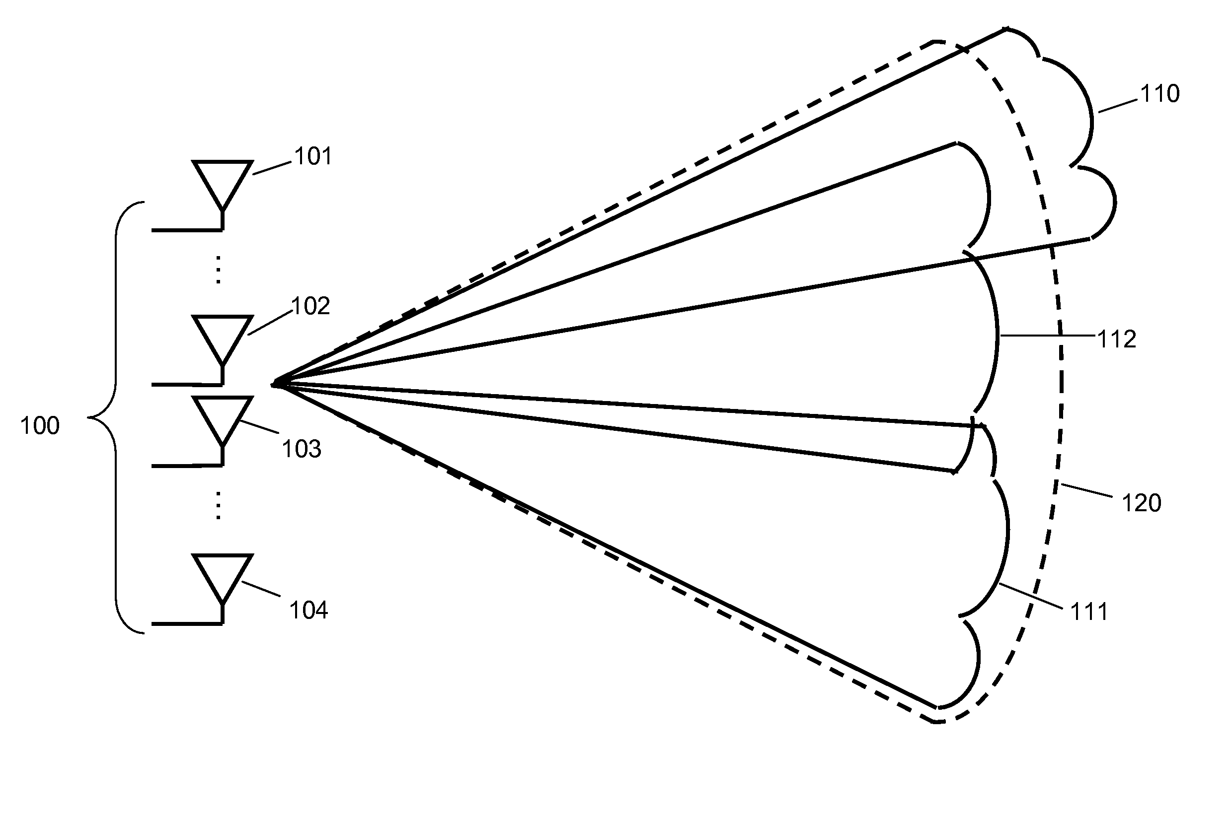
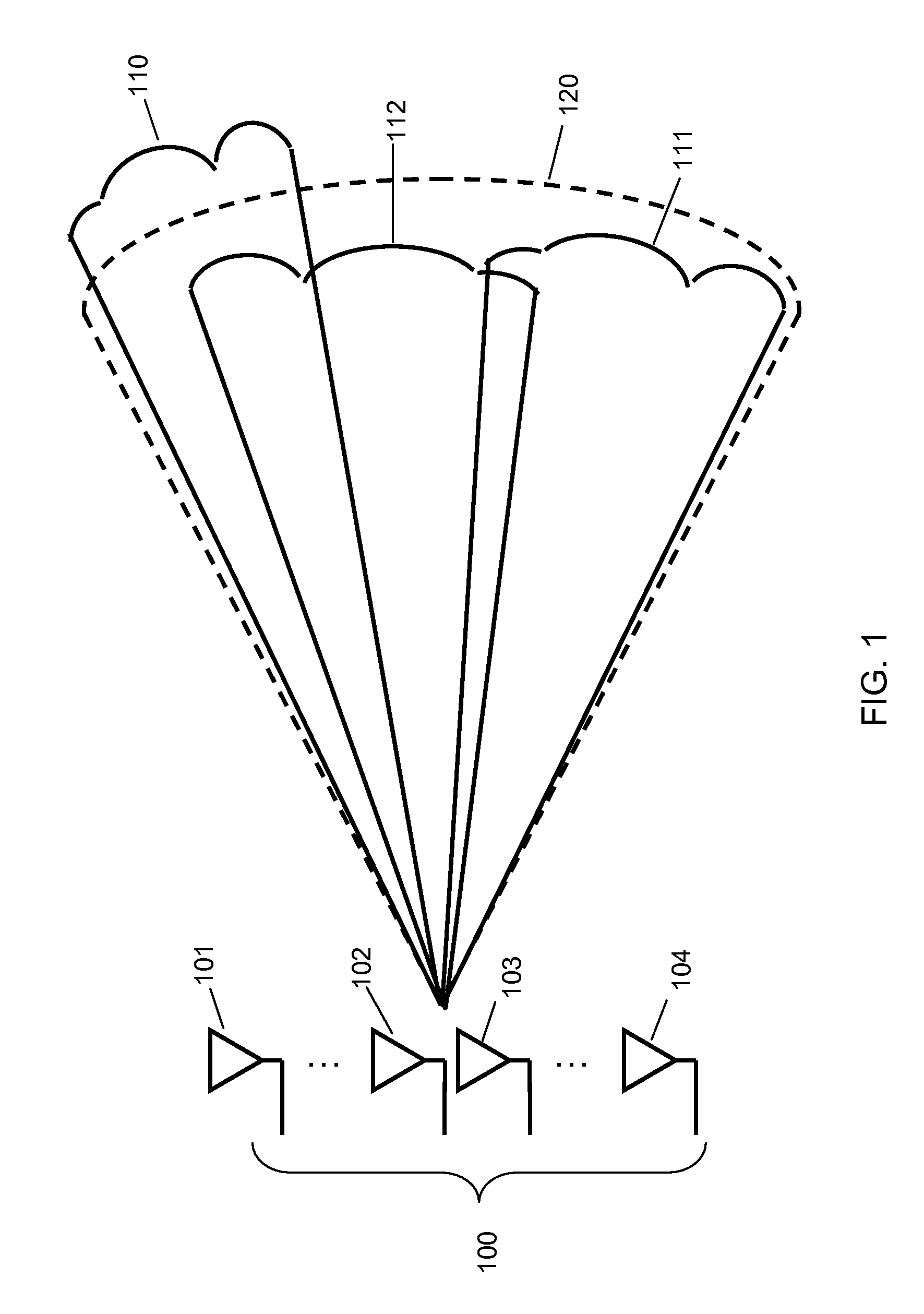
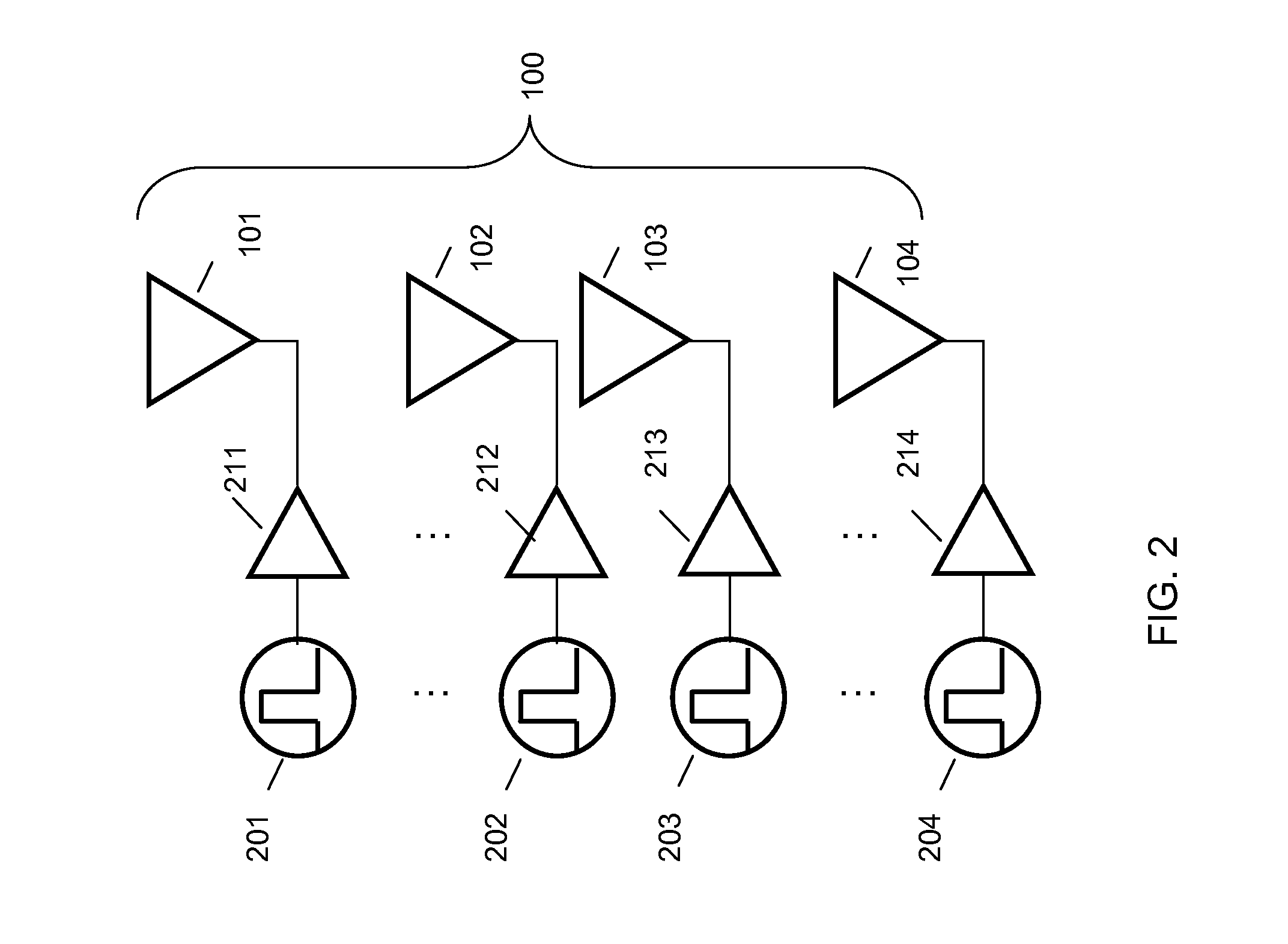
[0061]The preferred embodiment of the present invention is an active retrodirective transmit-receive system having a transmit waveform that provides the following characteristics: (1) a “stochastic” transmit beam that automatically fluctuates over the field-of-view (defined by the single-element beam pattern of a planar antenna array) without phase shifters or other electronic beam scanning devices, and (2) a determinism and phase coherence that can be used to carry out the signal processing and target acquisition functions of a modern radar including detection, range, bearing, and acquisition. Specifically, the waveform behaves in a random fashion over a time scale comparable to the inverse RF bandwidth of the system, but a deterministic fashion over a longer time scale [at least one round-trip time through free space] to provide for coherent signal processing in the receiver.

[0062]The preferred embodiment of the present invention employs pseudorandom modulated (PRM) waveforms. In ...


PUM


Abstract

Embodiments provide radio-frequency systems that can automatically detect, focus-on, and track objects in the environment without the need for expensive electronic scanning and phase-shifting components. Some embodiments are directed to retrodirective systems including: (1) quiescently broadcast pseudorandom-modulated radiation, such as pseudorandom bit sequences, in the absence of a target, over a field-of-view comparable to the beam solid angle of a single element in the transmit array; (2) a receive antenna element or array, in a desired spatial relationship with respect to the transmit antenna array, that receives reflected pseudorandom radiation from a target; and (3) an electronic signal-processing and feedback channel between the receive and transmit arrays that carries out cross-correlation between the received radiation and the transmitted pseudorandom signals and computes complex correlation coefficients to form a re-transmitted beam. Some embodiments are useful for short-range applications involving small and fast moving targets.

Description

RELATED APPLICATIONS[0001]This application claims benefit of U.S. Provisional Application No. 60 / 922,482 filed Apr. 9, 2007. This referenced application is incorporated herein by reference as if set forth in full herein.U.S. GOVERNMENT RIGHTS[0002]A portion of the inventions disclosed and potentially claimed herein were made with Government support under Contract Number W911 NF-05-C-0106. The Government has certain rights. Not all inventions disclosed herein were developed or conceived with government funding and it is not intended that the government attain rights in such inventions.FIELD OF THE INVENTION[0003]The present invention relates generally to electromagnetic radiation transmission and detection methods and apparatus related to a retrodirective antenna configuration, a “retrodirective” functionality, and a target detection capability. In the present context, “retrodirective” means that the radiation collected by the system receiver is used by the system to automatically tr...

Claims


Application Information

Patent Timeline
Patent Type & Authority Applications(United States)
IPC IPC(8): H01Q1/00
CPCH01Q3/2647
Inventor BROWN, ELLIOTT R.SINCLAIR, RODNEY F.
Owner PHYSICAL DOMAINS
Why Eureka
Try Eureka