Image processor and image processing method

a technology applied in the field of image processing and image processing method, can solve the problems of increasing the cost of image processing, the effect of increasing the cost, and not reducing the processing speed

Active Publication Date: 2011-04-14
CANON KK
View PDF10 Cites 13 Cited by
  • Summary
  • Abstract
  • Description
  • Claims
  • Application Information

AI Technical Summary

Benefits of technology

[0009]The object of the present invention is to solve the problems described above. In other words, the object of the present invention is to provide an image processor and image processing method that are capable of outputting images in multipass printing that have no fluctuation in image density or density unevenness due to deviation during printing, and are capable of outputting such images without a drop in processing speed or increase in cost.

Problems solved by technology

However, recently, by performing multipass printing, a new adverse effect of image due to deviation of print position among printing scans is viewed with suspicion.
Deviation of these dot groups is caused by fluctuation in the distance between the printing medium and ejection face (paper distance), fluctuation in the conveyed amount of the printing medium, and the like, when this happens, the dot coverage rate on the paper fluctuates, which causes density fluctuation and density unevenness of an image.
Therefore, when performing judgment over a somewhat large area, the dot coverage on the printing medium does not fluctuate much, and thus it is also difficult for changes to occur in the image density.
Therefore, it takes more time to complete quantization when compared with the case in which quantization is performed for just one gradation plane, and thus a new problem occurs in that the processing speed becomes slower.
In order to avoid this problem, a large capacity memory can be prepared, or a CPU can be prepared that has superior processing capability, however; the cost of the device then increases.

Method used


Image

  • Image processor and image processing method
  • Image processor and image processing method
  • Image processor and image processing method

Examples


embodiment 1

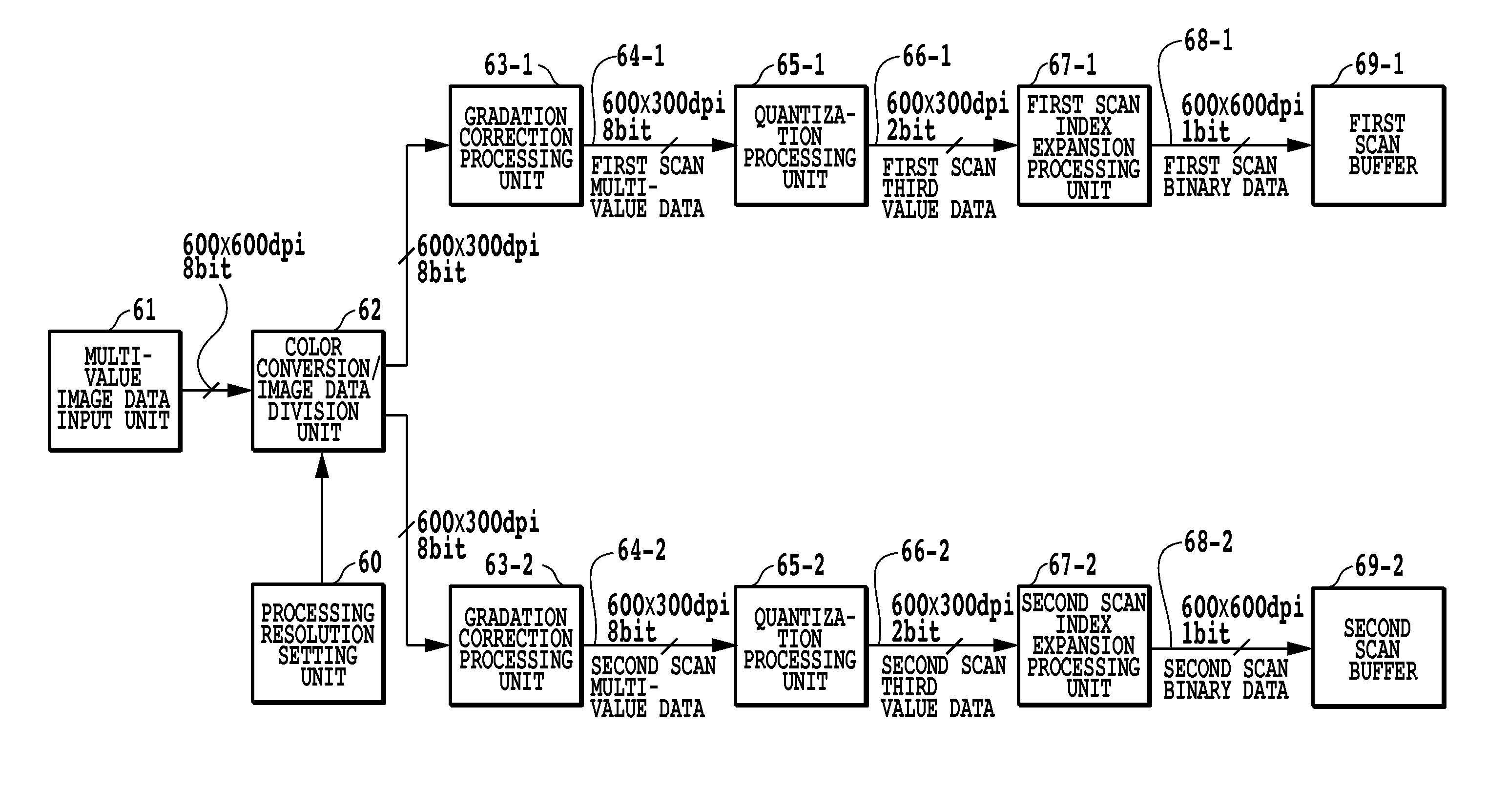
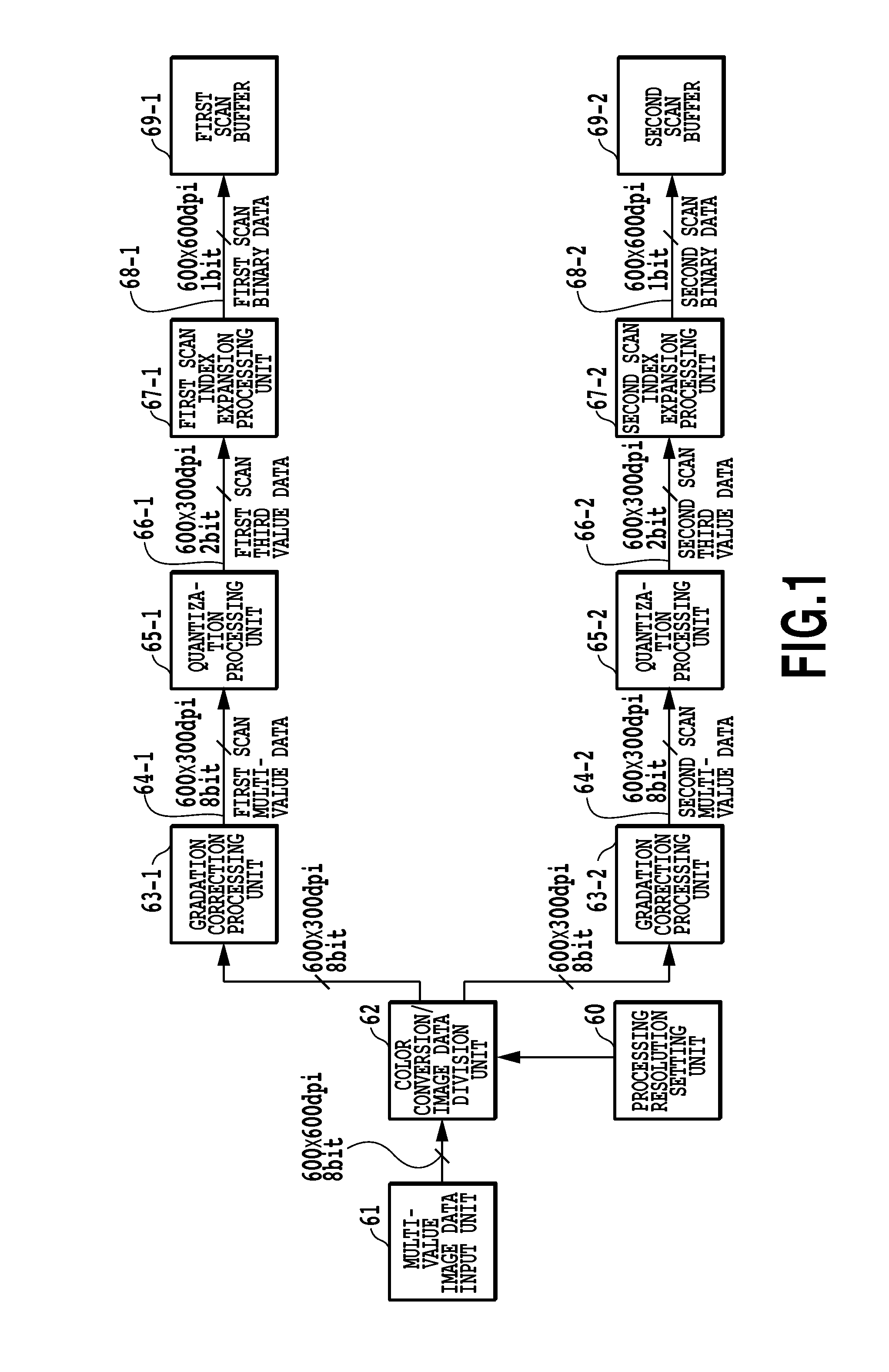
[0050]FIG. 1 is a block diagram for explaining the steps of the image processing of an embodiment in which an image is completed in the same area of a printing medium by using 2-pass multipass printing. In this embodiment, the control unit 3000 comprises a multi-value image data input unit (61), color conversion / image data division unit (62), processing resolution setting unit (60), gradation correction processing units (63-1, 63-2), and quantization processing units (65-1, 65-2).

[0051]In this embodiment, the RGB multi-value image data that is input to the multi-value image data input unit 61 from an external device is taken to be image data in which individual pixel for each color are expressed in 8 bits (256 values) and have a resolution of 600 dpi×600 dpi. In addition, the color conversion / image data division unit 62 converts this input image data (256-value RGB data) to 2 groups of multi-value image data (256-value density data) that corresponds to the ink color (CMYK). In this ...

embodiment 2

[0079]In the following, a second embodiment of the present invention will be explained. Generally, in a highlighted portion where graininess is noticeable, it is preferred to evenly disperse the few number of dots (1701, 1702) such that they have a fixed distance between them as illustrated in FIG. 8B. Moreover, in high-density portion where the highest density values are important, it is preferred that dots be filled in to an extent that there are no exposed areas of blank paper. In other words, it is desired that the ratio of areas of overlapping dots (dot overlap rate) be adjusted with good balance within a range such that density unevenness, graininess and insufficient density of the output image are not a problem.

[0080]However, in the method disclosed in Japanese Patent Laid-Open No. 2000-103088, quantization processing is performed for each plane without any correlation among the plurality of planes, and the dot overlap rate is set such that it depends on the quantization proc...

embodiment 3

[0106]In the second embodiment, a method was explained in which the color conversion / image data division unit adjusts the distribution rate in order to control the dot overlap rate. In this embodiment, the dot overlap rate is controlled by providing features to the quantization process when quantizing the plurality of multi-value density data that is generated by the color conversion / image data division unit. When doing this, the dot overlap rate may also be controlled by the quantization processing unit cooperating with adjustment of the distribution rate by the color conversion / image data division unit.

[0107]FIG. 15 is a block diagram for explaining image processing when performing multipass printing for completing an image in the same area of a printing medium by two printing scans. In this embodiment, except for the quantization processing unit 25, the construction is the same as that of the second embodiment that was explained using FIG. 14. Therefore, only the processing execu...


PUM


Abstract

Inputted image data is converted to M number of multi-value data having a lower resolution than the inputted image data, and after quantization processing has been performed for each of the M number of multi-value data, an image is printed by M number of relative movements (M-pass printing) that corresponds to the M number of quantized data. By doing so, when compared with the case in which a resolution reduction process is not performed, it is possible to suppress the number of pixels that become the object of quantization processing, and it becomes possible to output an image with no fluctuation in image density or density unevenness without a decrease in the processing speed.

Description

BACKGROUND OF THE INVENTION[0001]1. Field of the Invention[0002]The present invention relates to an image processor and image processing method that process multi-value image data that correspond to the same area in order to print an image in the same area by relatively moving a printing unit or a plurality of printing element groups a plurality of times with respect to the same area of a printing medium.[0003]2. Description of the Related Art[0004]In inkjet printing devices, a multipass printing method that prints by performing a plurality of printing scans of image data to be printed in the same area of a printing medium is known as a technique for reducing density unevenness and stripes. However, recently, by performing multipass printing, a new adverse effect of image due to deviation of print position among printing scans is viewed with suspicion. Here, deviation of the printing position among printing scans is, for example, deviation between a dot group that is printed in a fi...

Claims


Application Information

Patent Timeline
Patent Type & Authority Applications(United States)
IPC IPC(8): G06K15/02
CPCH04N1/40068
Inventor TSUCHIYA, OKINORIGOTO, FUMIHIROYAMADA, AKITOSHINAKATANI, AKIHIKOONO, MITSUHIROGOTO, FUMITAKAFUJITA, TAKASHIKAJIHARA, RIESANO, AYUMIISHIKAWA, TOMOKAZU
Owner CANON KK
Why Eureka
Try Eureka