Optical communication system and communication bandwidth control method

a communication system and optical communication technology, applied in the field of optical communication system configuration, can solve the problems of increasing the number of slave stations, affecting the quality of the signal required to have a real time nature, and increasing the interruption (standby) time of each onu, so as to increase the bandwidth use efficiency over the line-concentration optical fiber, reduce processing load on the olt side, and increase the number of accommodated slave stations

Inactive Publication Date: 2011-04-14
HITACHI LTD
View PDF4 Cites 32 Cited by
  • Summary
  • Abstract
  • Description
  • Claims
  • Application Information

AI Technical Summary

Benefits of technology

[0013]More specifically, the RE is inserted in a line concentration fiber interval in which the OLT is coupled to the optical splitter. The RE includes a measurement section which measures the transmission distance or the transmission time between the RE and the ONU, a determination section which, based on a transmission bandwidth request from the ONU, determines a timing for this ONU to transmit a signal, and a signal processing section which processes a signal received from the ONU and transmits the resulting signal to the OLT. When the OLT receives a signal transmission request from the ONU, the OLT determines a data amount (the width of a communication time frame) which the ONU can transmit at a certain time interval (hereinafter, may be referred to as a logical DBA cycle or a first DBA cycle), while the RE determines a time instance at which each ONU can transmit a signal in a physical DBA cycle (hereinafter, may be referred to as a second DBA cycle) shorter than the logical DBA cycle of the OLT. The RE controls the signal transmission timing from the ONU based on the logical DBA cycle and the physical DBA cycle so as to transmit the signal to the OLT in a form of a continuous signal, with a guard bit portion included before and after a burst signal going from the ONU to the OLT and a part of the received frame information deleted. Furthermore, a burst frame extending over the existing DBA (including communication timing determination) processing cycles is made available, so that the communication bandwidth of an uplink signal between the master station and the slave station is more effectively used.
[

Problems solved by technology

As a result, the waiting time after each ONU sends a transmission request and until it acquires a transmission permission becomes long, and the communication interruption (standby) time of each ONU will increase.
That is, the quality of the signal required to have a real time nature is affected, or the chann

Method used


Image

  • Optical communication system and communication bandwidth control method
  • Optical communication system and communication bandwidth control method
  • Optical communication system and communication bandwidth control method

Examples


Embodiment Construction

[0031]Hereinafter, the configuration and operation of a PON system according to the present invention will be described using the accompanying drawings, with the configuration and operation of a G-PON specified by ITU-T Recommendation G984.3 as an example.

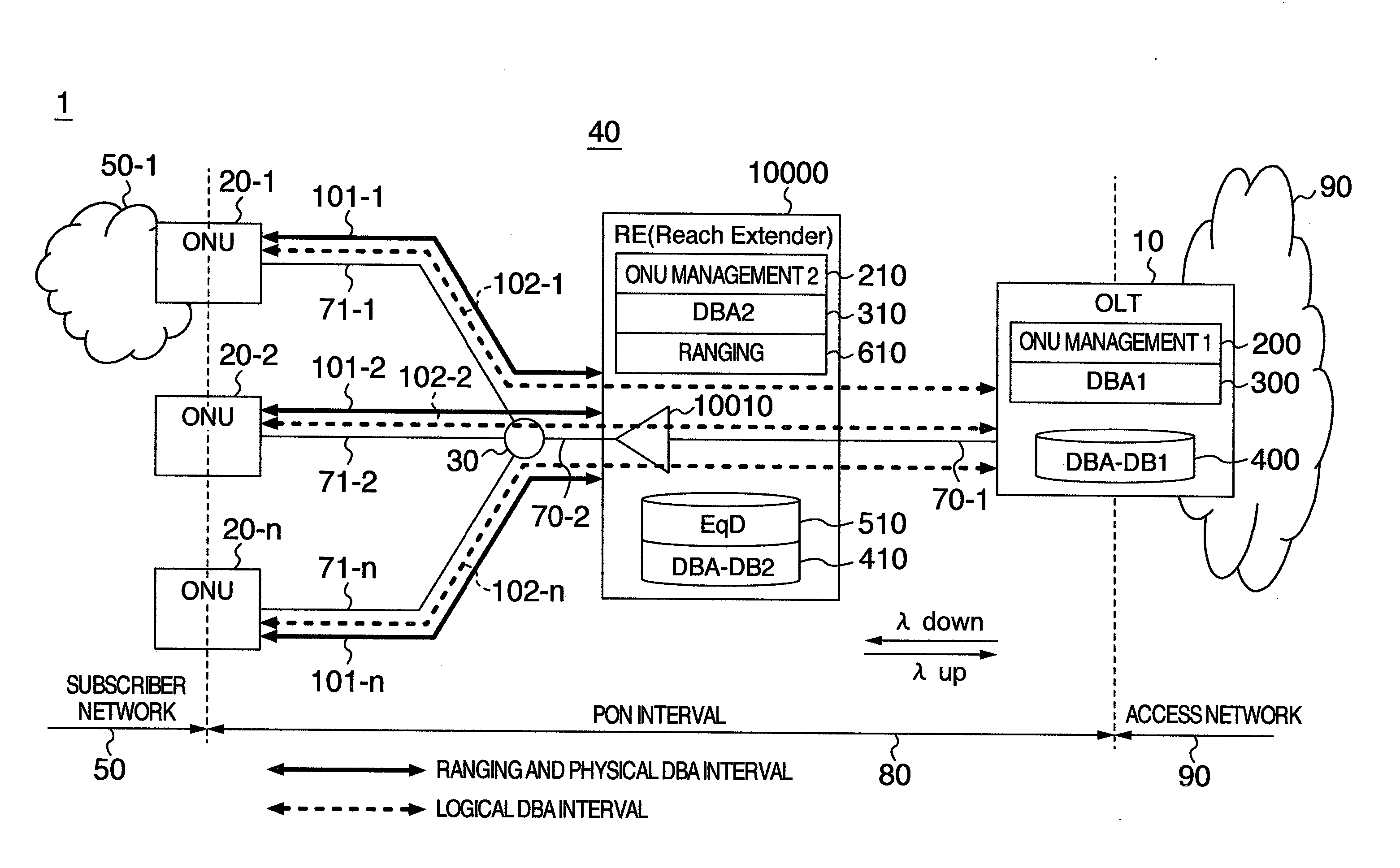
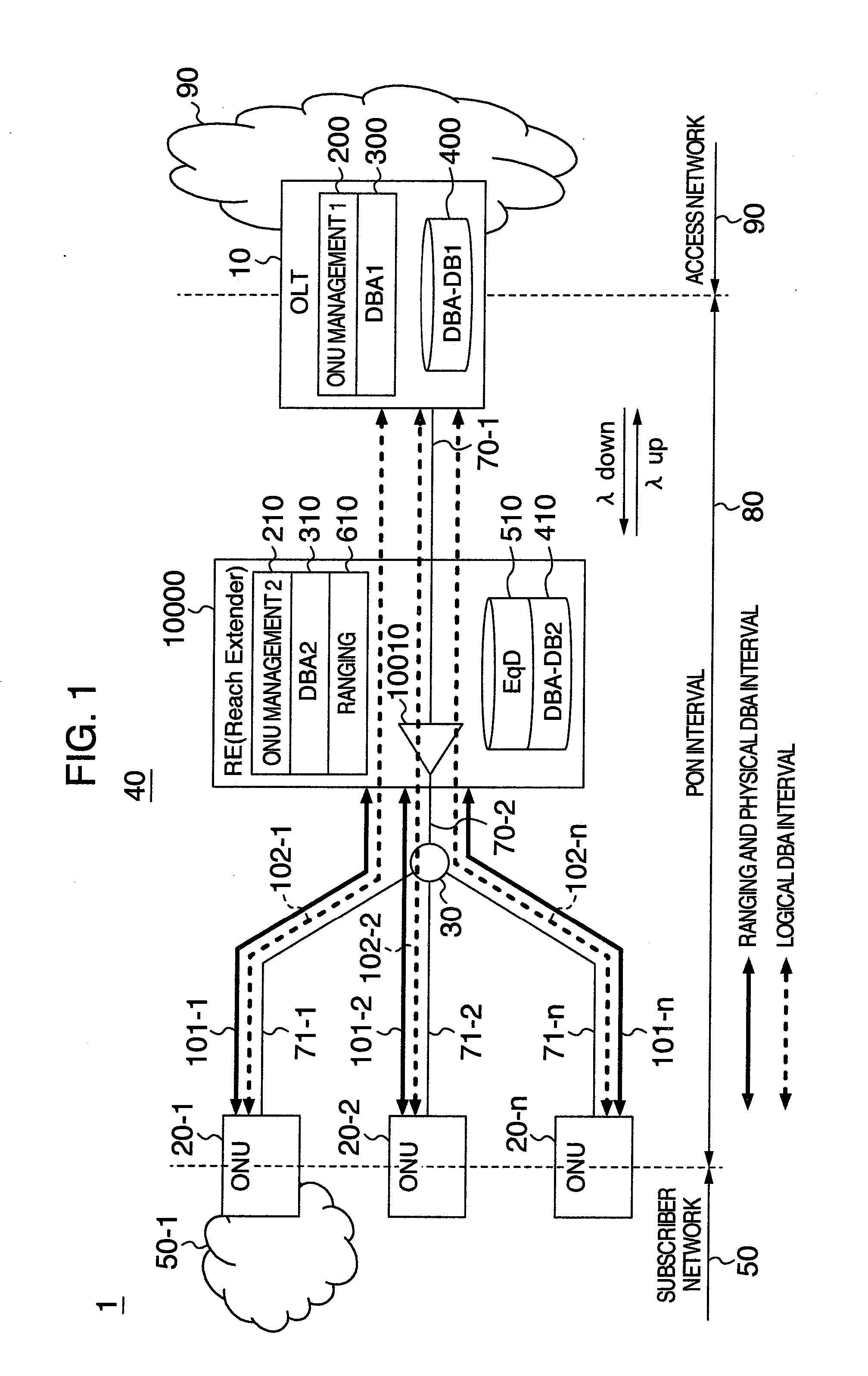
[0032]FIG. 1 is a network configuration diagram showing a configuration example of an optical access network using the PON of the present invention, and shows a configuration example when an RE is inserted into a line-concentration optical fiber of the PON.

[0033]A PON 40 comprises an optical line unit (OLT) 10, a plurality of optical network units (ONUs) 20-1-20-n, an optical splitter 30, a line-concentration optical fiber 70, a plurality of branch optical fibers 71-1-71-n, and a reach extender (RE) 10000 inserted between line-concentration optical fibers 70-1 and 70-2 in the middle of the line-concentration optical fiber 70. In the PON 40, an optical access network 1 is a network, wherein each of the ONUs 20-1-20-n is coupled to a...


PUM


Abstract

In the communication system, a master station is coupled to slave stations by a fiber network comprising a splitter and a reach extender, the master station includes a first bandwidth control section which determines, based on a request from each slave station, a first data amount of a signal transmitted in a first cycle, the reach extender includes: a distance measurement section which measures a distance or a time between the reach extender and each slave station; and a second bandwidth control section which determines a second data amount and transmission timing of a signal based on a request from each slave station and the first data amount, and each slave station transmits a signal with a data amount, which the first bandwidth control section determined based on a data amount and transmission timing determined in second cycles, to the master station in the first cycle.

Description

INCORPORATION BY REFERENCE[0001]The present application claims priority from Japanese applications JP2009-236792 filed on Oct. 14, 2009, the content of which is hereby incorporated by reference into this application.BACKGROUND OF THE INVENTION[0002]The present invention is directed to the configurations of an optical communication system in which a plurality of optical line units share an optical transmission line, and the methods of operating the same. In particular, the present invention relates to the configuration of an optical communication system excellent in system expandability, such as the capability to extend the transmission distance of the system and the capability to increase the number of accommodated subscribers, and the method of operating the same.[0003]With an increasing demand for communications utilizing a broadband, the access line for users is shifting to a large-capacity access line using an optical fiber, in place of the access techniques based on the telepho...

Claims


Application Information

Patent Timeline
IPC IPC(8): H04B10/08H04L12/44
CPCH04J3/0652H04Q2011/0073H04Q11/0067H04J3/0682
Inventor MIZUTANI, MASAHIKO
Owner HITACHI LTD
Why Eureka
Try Eureka