
Eureka
For R&D, Eureka makes reading and utilizing patents & technical documents easy.
Eureka AIR
Designed for self-driven R&D workflows. Generate viable solutions, solve complex R&D challenges, empower your innovation with AI.

Eureka Materials
Designed for material experts only. Revolutionize your material R&D, from search, analyze, to developing new materials.

TechResearch
Generate reliable direction feasibility study reports for your R&D in just a few steps.

TechSeek
Discover and master advanced knowledge NOW. Basics, ideas, possibilities, all at once.

TechMind
As an expert in R&D Theories, TechMind can generates customized viable solutions instantly.

TechRisk
Analyze your overall solution with one click, know your potential R&D risks in advance.

TechMonitor
Get weekly tech updates, stay abreast of the latest tech innovations and key insights.
Honeycomb filter
- Summary
- Abstract
- Description
- Claims
- Application Information
AI Technical Summary
Benefits of technology
Problems solved by technology
Method used
Image

Examples
first embodiment
[0064]The following description will discuss the first embodiment of the present invention which is one embodiment of the honeycomb filter.
[0065]The honeycomb filter of the present embodiment is provided by allowing the cell wall of the honeycomb structure to support zeolite.
[0066]As mentioned earlier, in the present description, a honeycomb structure in which zeolite is not supported on the cell wall is referred to as “honeycomb structure” and a honeycomb structure in which zeolite is supported on the cell wall is referred to as “honeycomb filter” to differentiate them from each other.
[0067]The honeycomb structure includes the honeycomb fired body, and the cell and the cell wall of the honeycomb structure also mean the cell and the cell wall of the honeycomb fired body.
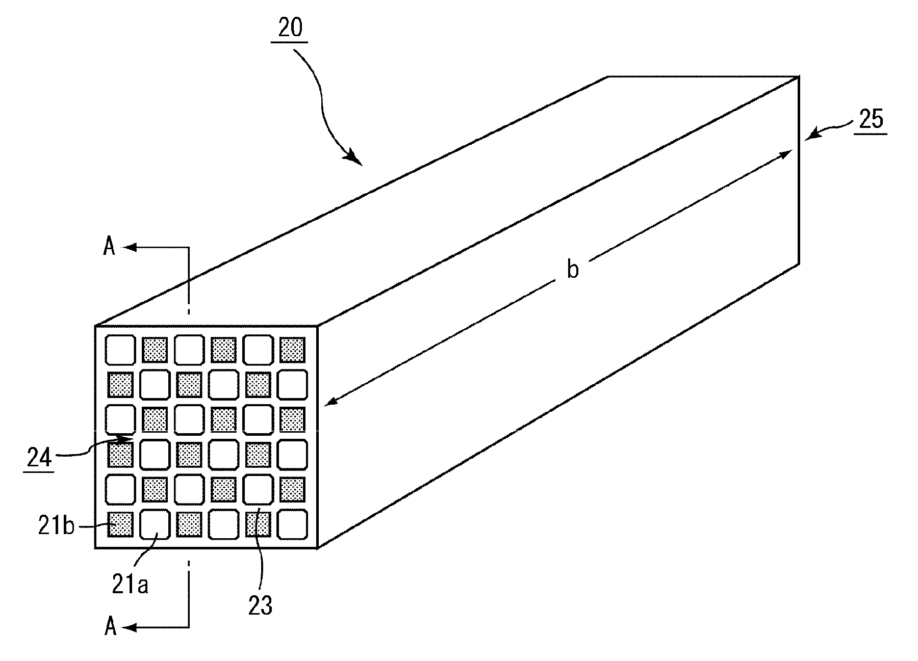
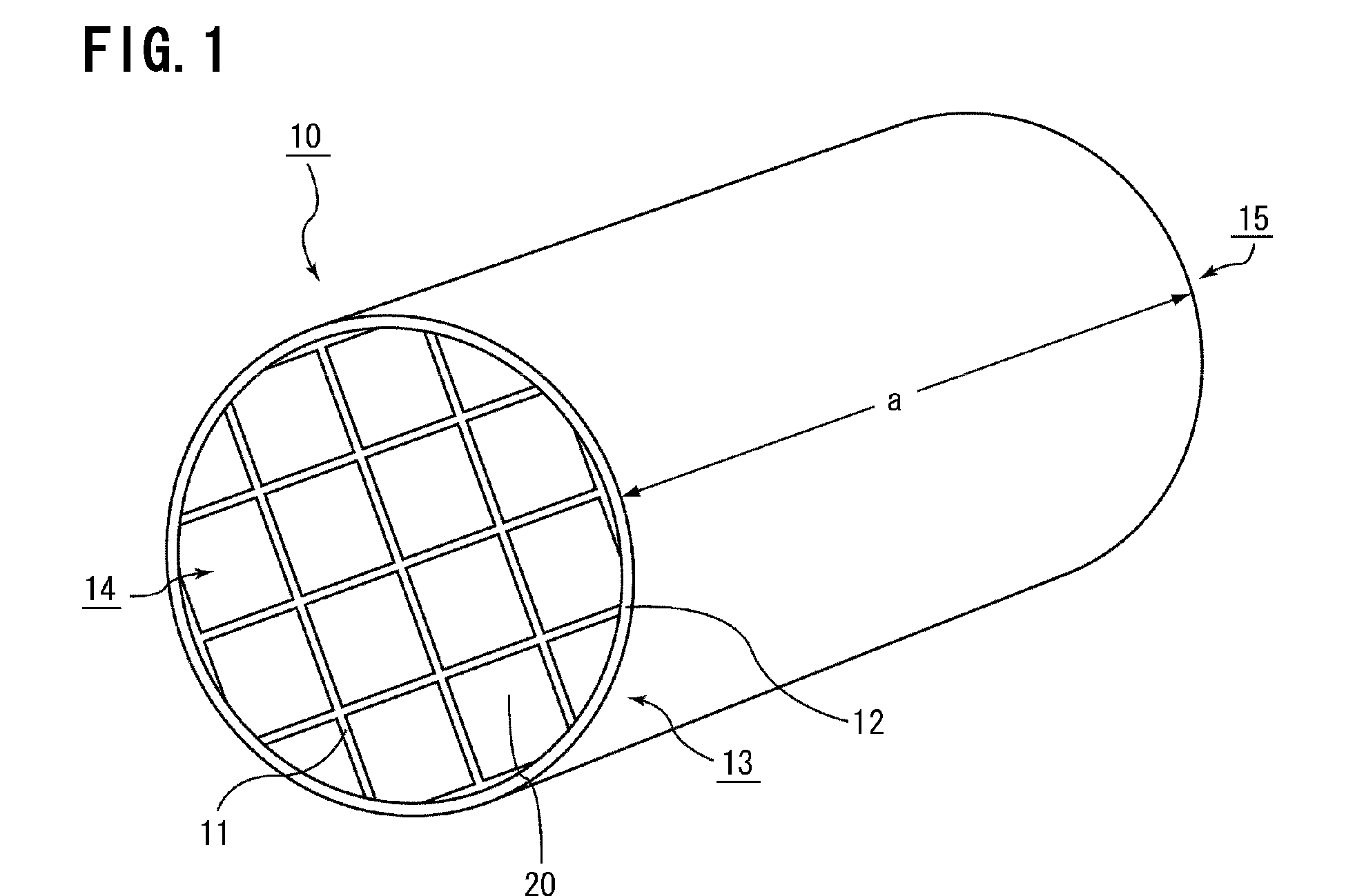
[0068]FIG. 1 is a perspective view that schematically shows one example of a honeycomb structure forming the honeycomb filter according to the first embodiment of the present invention.
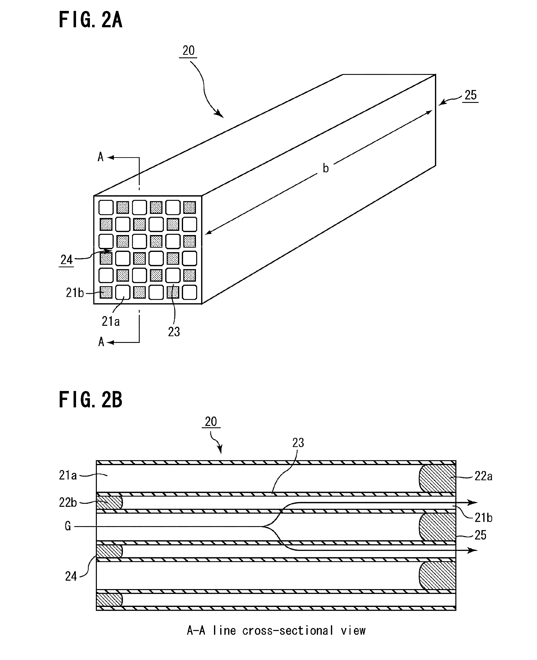
[0069]FIG. 2A is a perspective ...
example 1
[0182]A sufficient amount of water is mixed with β-type zeolite powder (average particle diameter: 2 μm) ion-exchanged with an iron ion and then stirred to prepare a zeolite slurry. The honeycomb structure 1a was dipped in the zeolite slurry with one end side facing down for one minute. Thereafter, the resulting honeycomb structure 1a was dried at 110° C. for one hour, and further fired at 700° C. for one hour so that a zeolite supporting layer was formed.
[0183]The procedure of dipping in the zeolite slurry, drying and firing was repeated so that the amount of the formed zeolite supporting layer reached 120 g per one liter of the apparent volume of the honeycomb structure.
[0184]Through the above procedure, a honeycomb filter having a zeolite supporting amount of 120 g / L (apparent volume) was manufactured.
examples 2 to 7
, Reference Example 1, Comparative Examples 1 to 5
[0185]Honeycomb filters were manufactured in Examples 2 to 7, Reference Example 1, and Comparative Examples 1 to 5, by allowing the honeycomb structures manufactured by respectively using the base materials shown in Tables 2-1 and 2-2 to support zeolite in respective amounts shown in Tables 2-1 and 2-2.
[0186]The amounts of zeolite to be supported were controlled by changing the number of times to repeat the dipping into zeolite slurry, drying or firing.
(Measurement of Nox Conversion Rate)
[0187]NOx conversion rate was measured on the honeycomb filters manufactured in Examples, Reference Example, and Comparative Examples.
[0188]For measurement of NOx conversion rate, each of the honeycomb filters manufactured in Examples, Reference Example, and Comparative Examples was cut by a diamond cutter to produce a single honeycomb fired body (34.3 mm×34.3 mm×150 mm). The cut-out honeycomb fired body was further cut shortened to prepare a short-l...
PUM
| Property | Measurement | Unit |
|---|---|---|
| Fraction | aaaaa | aaaaa |
| Fraction | aaaaa | aaaaa |
| Fraction | aaaaa | aaaaa |
Abstract
Description
Claims
Application Information
 - R&D Engineer
- R&D Manager
- IP Professional
- Industry Leading Data Capabilities
- Powerful AI technology
- Patent DNA Extraction
Browse by: Latest US Patents, China's latest patents, Technical Efficacy Thesaurus, Application Domain, Technology Topic, Popular Technical Reports.
© 2024 PatSnap. All rights reserved.Legal|Privacy policy|Modern Slavery Act Transparency Statement|Sitemap|About US| Contact US: help@patsnap.com