Exhaust emission control device

a technology of exhaust gas and control device, which is applied in the direction of mechanical equipment, machines/engines, transportation and packaging, etc., can solve the problems of affecting the mountability of vehicles, and achieve the effects of enhancing the mixing with the exhaust gas, favorable dispersion, and excellent effects

Active Publication Date: 2011-04-21
HINO MOTORS LTD
View PDF11 Cites 11 Cited by
  • Summary
  • Abstract
  • Description
  • Claims
  • Application Information

AI Technical Summary

Benefits of technology

An exhaust emission control device of the invention mentioned above can have a variety of excellent effects and advantages as mentioned below.
(I) Swirling flows can be effectively formed in the mixing pipe to favorably disperse the urea water, so that the urea water can be favorably dispersed even if the flow rate of the exhaust gas is increased to thereby enhance the mixing with the exhaust gas. Before accession to the selective reduction catalyst, mist particles of the urea water can be effectively made smaller in size for early pyrolysis into ammonia and carbon dioxide gas.
(II) Without turbulence and extreme throttling in flow cross-area of the flow of the exhaust gas, the exhaust gas can be smoothly guided from the exit end of the particulate filter to the entry end of the mixing pipe, which suppresses increase in exhaust resistance and lowers the pressure loss.
(III) When the scroll-shape is provided in a space between the entry end of mixing pipe and the downstream end of the gas gathering chamber encircling the entry end of the mixing pipe in accord with the flow of the exhaust gas guided around the entry end of the mixing pipe, the flow of the exhaust gas can be guided by the scroll-shape to swirl in one direction around the entry end of the mixing pipe, so that swirling flow formation of the exhaust gas is further facilitated and the mixing of the urea water with the exhaust gas in the mixing pipe is further enhanced.

Problems solved by technology

However, arrangement of the particulate filter and the selective reduction catalyst substantially spaced apart from each other will extremely impair the mountability on a vehicle.

Method used


Image

  • Exhaust emission control device
  • Exhaust emission control device
  • Exhaust emission control device

Examples


Embodiment Construction

An embodiment of the invention will be described in conjunction with the drawings.

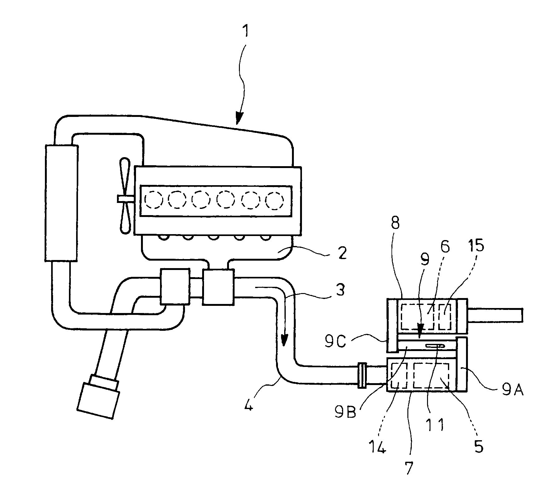
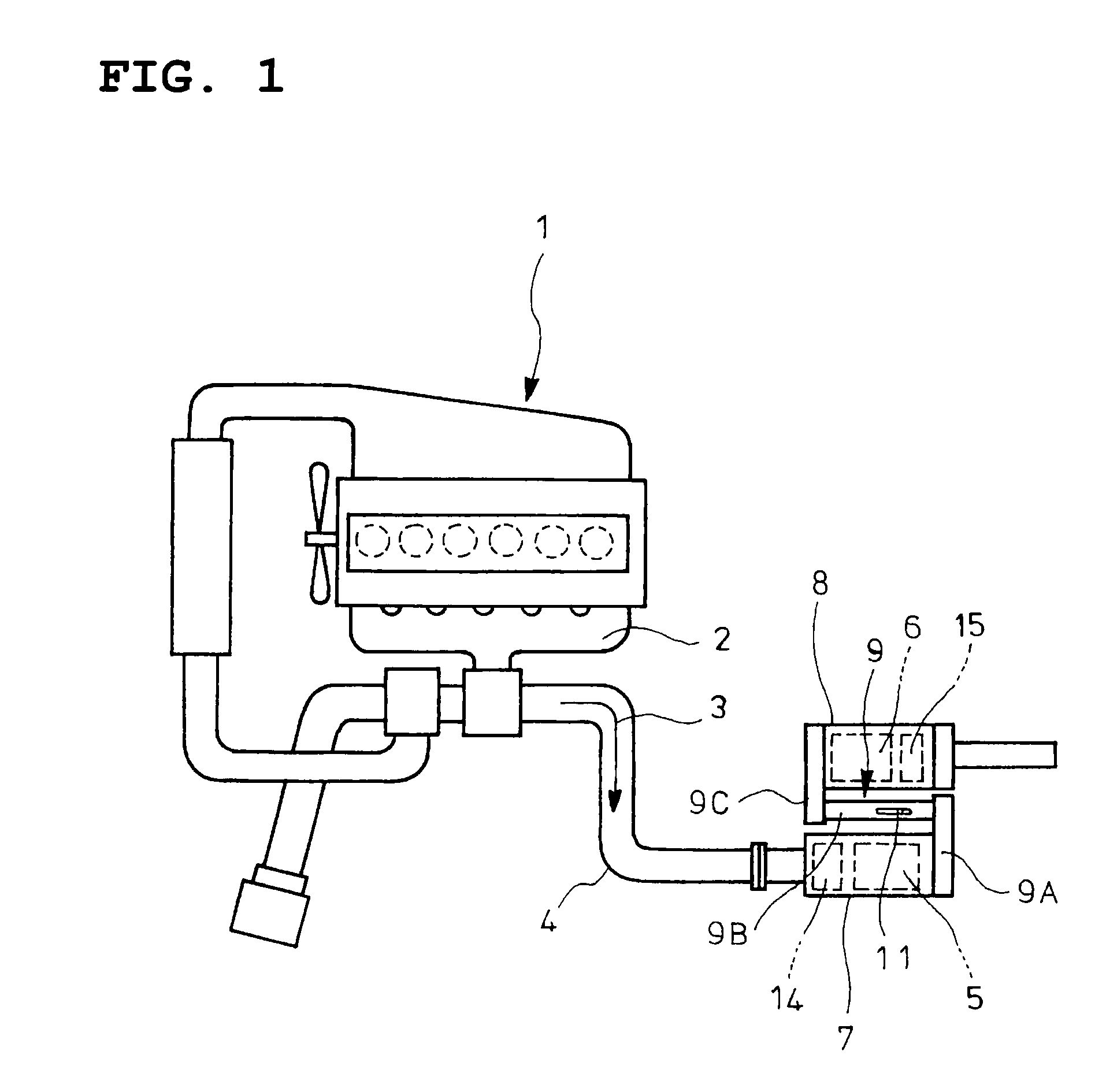
FIGS. 4 and 5 show the embodiment of the invention which is directed to an exhaust emission control device constructed substantially similar to that shown in FIGS. 1 and 2 mentioned in the above, a gas gathering chamber 9A and a mixing pipe 9B constituting together an upstream portion of the communication passage 9 being changed as disclosed below.

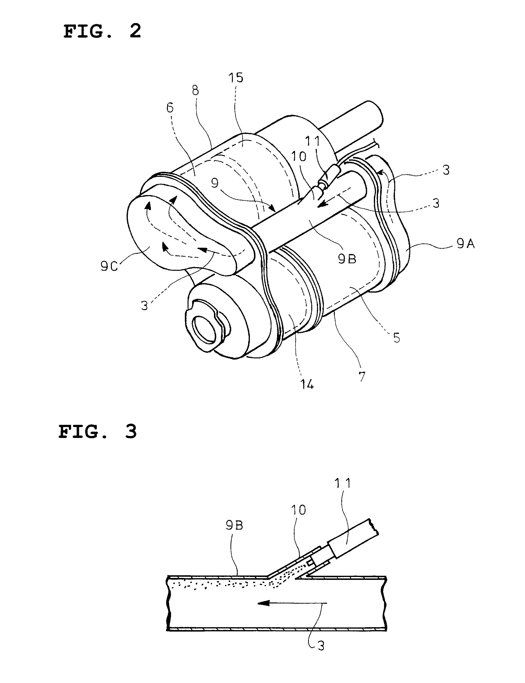
Specifically, in the embodiment illustrated, a downstream end 9a of the gas gathering chamber 9A is connected to an entry end of the mixing pipe 9B to cover a periphery of the entry end of the mixing pipe 9B with a required intervening space and to close the open entry end of the mixing pipe 9B. Moreover, in the space between the entry end of the mixing pipe 9B and the downstream end 9a of the gas gathering chamber 9A encircling the entry end of the mixing pipe 9B, a scroll-shape is provided by a first partition 16, which is described hereinafter, in accord w...


PUM

PropertyMeasurementUnit
distanceaaaaaaaaaa
sizeaaaaaaaaaa
flow rateaaaaaaaaaa

Abstract

An object of the invention is to provide an exhaust emission control device capable of favorably dispersing urea water for improved mixing with exhaust gas even if a flow rate of the exhaust gas is increased. An entry end of a mixing pipe is formed with a first opening at a position near an exit side of a particulate filter and is formed with a second opening at a position away from the exit side of the particulate filter and diametrically opposite to the first opening. Arranged in a downstream end of a gas gathering chamber are a first partition which guides all of the flow of exhaust gas from the particulate filter into a one-way swirling flow around the entry end of the mixing pipe, a second partition which divides the flow of the exhaust gas guided by the first partition into two to cause an inner one of the divided swirling flows to tangentially enter into the first opening and a third partition which causes the remaining outer swirling flow to tangentially enter into the second opening.

Description

TECHNICAL FIELDThe present invention relates to an exhaust emission control device.BACKGROUND ARTIt has been recently proposed that a particulate filter for capturing particulates in exhaust gas is incorporated in an exhaust pipe and a selective reduction catalyst capable of selectively reacting NOx with ammonia even in the presence of oxygen is arranged downstream of the particulate filter, urea water as reducing agent being added between the selective reduction catalyst and the particulate filter, thereby attaining lessening of both the particulates and NOx.Such addition of the urea water to the selective reduction catalyst is conducted between the particulate filter and the selective reduction catalyst. Thus, in order to ensure sufficient reaction time for pyrolysis of the urea water added to the exhaust gas into ammonia and carbon dioxide gas, it is necessary to prolong a distance between a urea water added position and the selective reduction catalyst. However, arrangement of t...

Claims


Application Information

Patent Timeline
Patent Type & Authority Applications(United States)
IPC IPC(8): F01N3/035F01N1/00
CPCB01F3/04049B01F5/0057F01N3/035F01N3/2066F01N13/009F01N2470/18F01N2610/02Y02T10/24F01N13/0097F01N2240/20Y02T10/12B01F23/2132B01F25/10
Inventor KOWADA, MINORU
Owner HINO MOTORS LTD
Why Eureka
Try Eureka