Load driving circuit and multi-load feedback circuit

a feedback circuit and load technology, applied in the direction of pulse technique, process and machine control, instruments, etc., can solve the problems of achieve the effect of improving efficiency, stable light emission, and lowering the efficiency of the led driving apparatus

Active Publication Date: 2011-04-21
GREEN SOLUTION TECH CO LTD
View PDF6 Cites 25 Cited by
  • Summary
  • Abstract
  • Description
  • Claims
  • Application Information

AI Technical Summary

Benefits of technology

[0007]In view of that, to ensure stable light emissions for the LED module, the conventional constant voltage driving apparatus for LEDs provides a driving voltage higher than the required voltage, yet the overly high driving voltage may cause lowered efficiency of the LED driving apparatus. The present invention is directed to resolve the efficiency issue of the LED driving apparatus by, in accordance with the voltage level associated with one or more current balancing terminals having insufficient voltage level in the current balancing circuit of the LED driving apparatus, adjusting the electric power required to drive the LED module in the LED driving apparatus, such that the LED driving apparatus is capable of balancing the current flowing through each LED as well as improving efficiency.

Problems solved by technology

In view of that, to ensure stable light emissions for the LED module, the conventional constant voltage driving apparatus for LEDs provides a driving voltage higher than the required voltage, yet the overly high driving voltage may cause lowered efficiency of the LED driving apparatus.

Method used


Image

  • Load driving circuit and multi-load feedback circuit
  • Load driving circuit and multi-load feedback circuit
  • Load driving circuit and multi-load feedback circuit

Examples


first embodiment

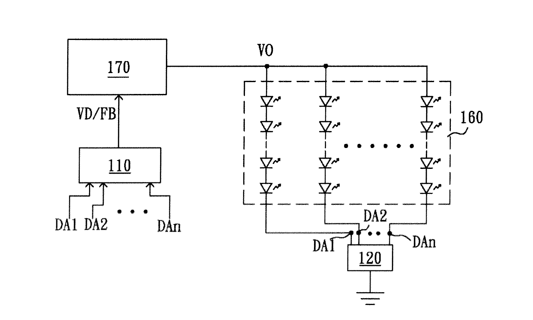
[0024]Next, refer to FIG. 3, wherein a schematic diagram of the multi-load feedback circuit according to the present invention is shown. The present multi-load feedback circuit 210 comprises a plurality of semiconductor switches 212 and a determining circuit 214. Each semiconductor switch has a first terminal, a second terminal and a third terminal. The first terminals are coupled to a common reference voltage VREF. The second terminals are individually coupled to the plurality of current balancing terminals DA1˜DAn of the current balancing circuit 220; that is, coupled to the plural LED strings in the LED module 160. The third terminals are coupled with each other and also coupled to the determining circuit 214, thereby generating a detection signal VD to the determining circuit 214.

[0025]The current balancing circuit 220 includes a plurality of current balancing units 222, with each current balancing unit 222 including a transistor switch SW, a resistor R and an error amplifier EA...

second embodiment

[0029]Refer next to FIG. 4, wherein a schematic diagram of the multi-load feedback circuit according to the present invention is shown. The multi-load feedback circuit 310 comprises a plurality of semiconductor switches 312, an error amplifier 314, a resistor 316 and a transistor switch 318. Each semiconductor switch 312 has a first terminal, a second terminal and a third terminal. The first terminals are coupled to a common reference voltage VREF. The second terminals are individually coupled to the plurality of current balancing terminals DA1˜DAn of the current balancing circuit 320. The third terminals are coupled with each other and also coupled to the error amplifier 314 thereby generating a detection signal VD to the error amplifier 314. In the present embodiment, the circuits and operations of the semiconductor switch 312 is identical to which of the semiconductor switch 212 illustrated in FIG. 3, descriptions thereof are thus omitted for brevity.

[0030]The most significant di...

third embodiment

[0031]Subsequently, refer to FIG. 5, wherein a schematic diagram of the multi-load feedback circuit according to the present invention is shown. Compared with the multi-load feedback circuit 212 depicted in FIG. 3, each gate of the MOSFETs', having the sources thereof coupled to the current balancing terminals DA1˜DAn, is coupled to the corresponding current balancing terminal, rather than the common reference voltage VREF, so the MOSFET is maintained in a cutoff state. When the level at the current balancing terminal is lower than the common reference voltage VREF by a predetermined voltage difference thereby causing the corresponding multi-load feedback circuit 412 to be in a conducting state, the signal of the current balancing terminal will be passed to the inverse terminal of the comparator 414 through the body diode of the MOSFET in cutoff and another MOSFET conducted. As a result, the multi-load feedback circuit 412 according to the present embodiment can, as the multi-load f...


PUM


Abstract

A load driving circuit and a multi-load feedback circuit is disclosed. The load driving circuit and the multi-load feedback circuit are adapted to drive a LED module that has a current balancing circuit for balancing the currents flowing through LEDs. The load driving circuit and the multi-load feedback circuit modules the electric power transmitted by the LED driving apparatus to a LED module according to voltage level(s) of current balancing terminals having insufficient voltage in the current balancing circuit, and so the voltage levels of the current balancing terminals are higher than or equal to a preset voltage level, further increasing the efficiency thereof.

Description

BACKGROUND OF THE INVENTION[0001](1) Field of the Invention[0002]The present invention relates to a load driving circuit and a multi-load feedback circuit; in particular, it relates to a load driving circuit and a multi-load feedback circuit used to drive plural Light Emitting Diode strings.[0003](2) Description of the Prior Art[0004]Refer first to FIG. 1, wherein a schematic diagram of a conventional constant current driving apparatus for LEDs is shown. The illustrated LED constant current driving apparatus comprises a current balancing circuit 10, a LED module 60 and an electrical power supply 70. The electrical power supply 70 stabilizes the output voltage VOUT through a voltage feedback signal VFB generated by a voltage feedback circuit. The LED module 60 has plural LED strings connected in parallel between the electrical power supply 70 and the current balancing circuit 10. The current balancing circuit 10 has a current setting resistor 11 as well as a current mirror composed o...

Claims


Application Information

Patent Timeline
Patent Type & Authority Applications(United States)
IPC IPC(8): H05B41/36H03K17/56H03K17/687H03K17/60
CPCH05B33/0827H05B45/46
Inventor WANG, CHEN-HSUNGYU, CHUNG-CHELEE, LI-MINSHIU, SHIAN-SUNG
Owner GREEN SOLUTION TECH CO LTD
Why Eureka
Try Eureka