Isolating RFID Reader

a technology of rfid reader and reader, which is applied in the field of automatic identification and data collection, can solve the problems of not being able to identify multiple tags over a long distance or about a broad area, the reader does not have any control over which tags it can wake up, and cannot identify a single item among a group of items within the field of radio effectiveness, etc., to achieve the effect of long transmit distan

Inactive Publication Date: 2011-04-21
TAVSHIKAR MILIND M
View PDF13 Cites 15 Cited by
  • Summary
  • Abstract
  • Description
  • Claims
  • Application Information

AI Technical Summary

Benefits of technology

[0013]In another aspect, the characteristics of the reader is such that it can detect the presence of multiple Passive RFID tags present in its field of radiation and at the same time it is able to isolate a single tag within the group.
[0014]In one embodiment the reader is able to singularly identify a particular tag of interest and eliminate other tags present in adjacent areas within a close proximity of the tag of interest but within the readers field of radiation.
[0015]In another embodiment the reader is able to read barcodes and passive RFID tags using its RF module and at the same time transmit the acquired data to the backend system using its controller module over UHF frequencies achieving a long transmit distance and without the need to deploy expensive WiFi or GPRS technologies. Optical module of the reader can scan barcodes and RF module can read tags simultaneously. For example, when one has a pallet of boxes with each box having a UHF RFID tags and a barcodes on each box. If one of the boxes needs to be removed from the pallet due to a visual damage and all others need to be counted, our reader can scan the barcode of that particular damaged box on the pallet using the optical module and count all boxes on the pallet using the RF module in a single scan.

Problems solved by technology

While these systems allow individual recognition of tags over short distance, they cannot be used to identify multiple tags over a long distance or about a broad area.
These systems can identify multiple items from a long distance, but cannot identify a single item amongst a group of items within the field of radio effectiveness.
Thus, a reader does not have any control over which tags it can wake up.

Method used


Image

  • Isolating RFID Reader
  • Isolating RFID Reader
  • Isolating RFID Reader

Examples


Embodiment Construction

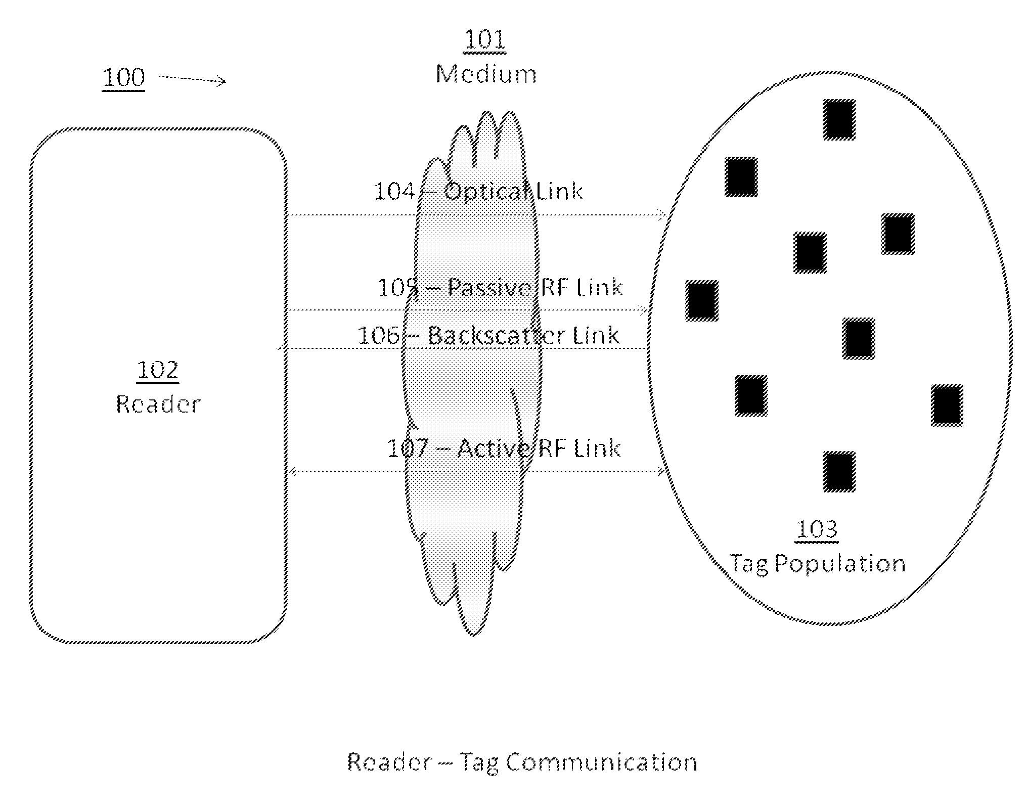
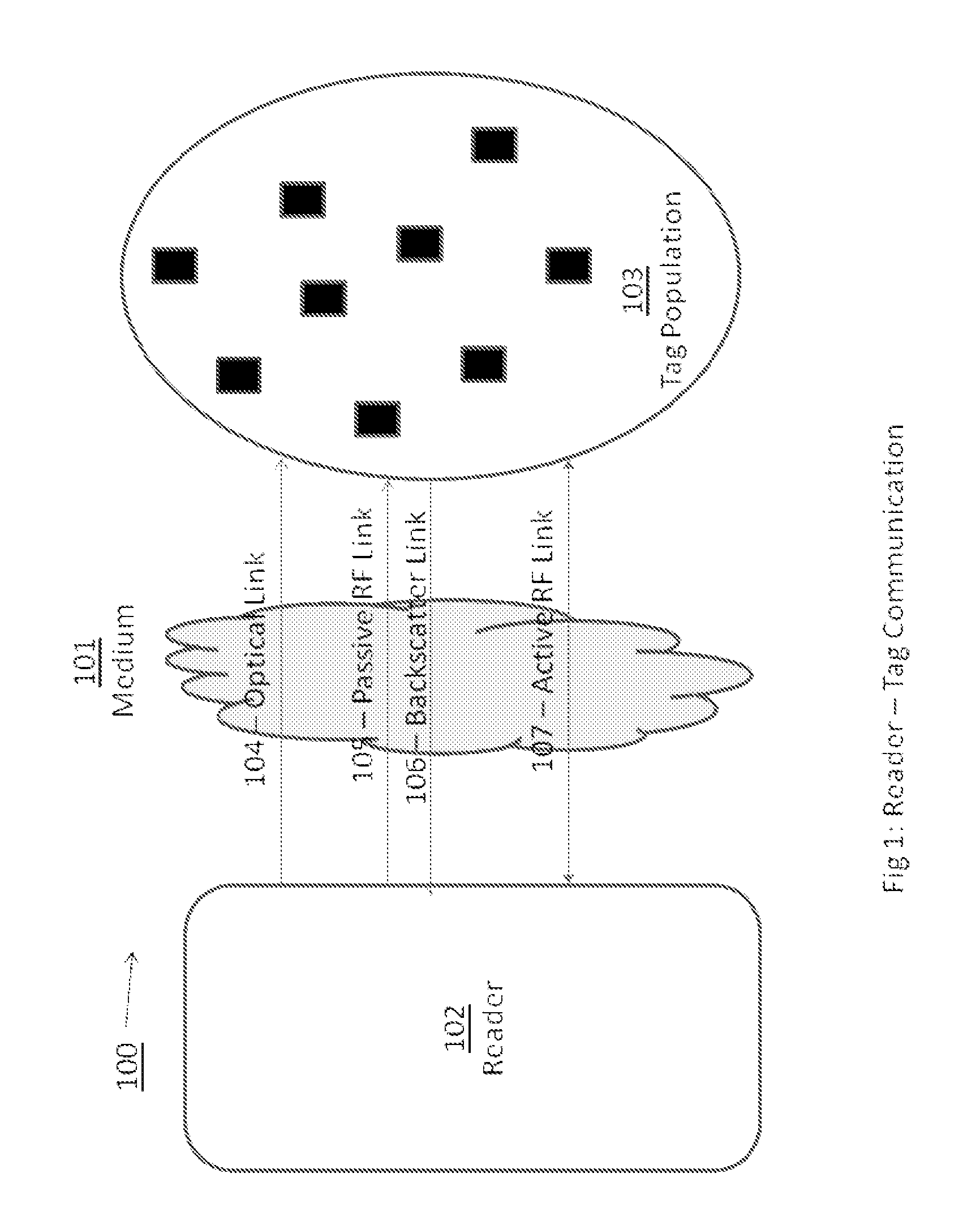
[0025]FIG. 1 is an illustrative example of an environment 100 in which an automatic identification and data collection system may operate. The system includes a reader 102 and a population of tags 103 that communicate with one another through one or more mediums 101 and using communication links 104,105,106 and 107. While described herein as wireless links using radio-frequency signals, these links are illustrative only and may include other links such as wired, cellular, optical and others. The medium can be free space or some other medium capable of supporting communication between the reader 102 and the tag population 103. In one embodiment the medium may also carry reflected radio waves and communicate over a variety of frequency ranges.

[0026]The reader 102 transmits data (and, in some cases, power) to the tag population 103 using an optical carrier wave. The beam of light may be in a visible or invisible spectrum, and the data is typically modulated onto the optical carrier wav...


PUM


Abstract

Systems and methods for using a multimodal handheld reader are described. The reader can be used to read non electronic labels, passive RFID tags using backscatter modulation techniques and battery based active RFID tags using a single handheld. The reader deploys a multiplexed antenna design and thereby contains a method to read a group of passive RFID tags and at the same time the reader can isolate a single passive RFID tag from amongst a group of passive RFID tags within close proximity. All such passive RFID tags use backscatter modulation techniques and are in the readers own RF zone.

Description

FIELD OF THE INVENTION [0001]The invention relates generally to automated object identification and data collection, and more specifically to apparatuses and methods for automated identification and data collection using radio waves at ultra-high frequencies (UHF).BACKGROUND OF THE INVENTION[0002]One example of automated identification and data collection (AIDC) technology is conventional radio-frequency identification (RFID) systems in which electronic tags transmit (or reflect) radio waves to an electronic reader. The received information is used to reference a database of known tags to identify a particular item. Another common example is a barcode (or other optical design or character set) reader that uses optical character recognition to read and recognize a unique identifier.[0003]Often, the various systems and methods used in AIDC implementations are categorized as either short range or long range, depending on the range at which a reader can read or recognize data that resid...

Claims


Application Information

Patent Timeline
Patent Type & Authority Applications(United States)
IPC IPC(8): H04Q5/22G06K7/10H04B10/00
CPCG06K7/0004G06K7/0008G06K7/10079H04Q2213/13095G06K7/10346G06K19/0728G06K7/10316
Inventor TAVSHIKAR, MILIND M.
Owner TAVSHIKAR MILIND M
Why Eureka
Try Eureka