Two-shaft extruder

a two-shaft extruder and extruder technology, applied in dough extruding machines, dough shaping, manufacturing tools, etc., can solve problems such as complicated constructions

Inactive Publication Date: 2011-04-21
MORIYAMA
View PDF60 Cites 8 Cited by
  • Summary
  • Abstract
  • Description
  • Claims
  • Application Information

AI Technical Summary

Benefits of technology

[0019]According to the third characterizing feature of the present invention, in addition to the second characterizing feature described above, a plurality of sets of the first abutment members and the second abutment members are provided along the longitudinal direction of each rotor shaft;
[0020]the projecting portions of the first abutment member belonging in a certain set are made different in position peripherally as seen in the axial direction of the one rotor shaft than the projecting portions of the first abutment member belonging in another set adjacent thereto; and
[0021]the projecting portions of the second abutment member belonging in a certain set are made different in position peripherally as seen in the axial direction of the other rotor shaft than the projecting portions of the second abutment member belonging in another set adjacent thereto.
[0022]That is, since a plurality of sets of the first abutment members and the second abutment members are provided along the longitudinal direction of each rotor shaft, the projecting portions of the first abutment member belonging in a certain set are made different in position peripherally as seen in the axial direction of the one rotor shaft than the projecting portions of th...

Problems solved by technology

In these ways, the construct...

Method used


Image

  • Two-shaft extruder
  • Two-shaft extruder
  • Two-shaft extruder

Examples


first embodiment

[0040]Next, a two-shaft extruder relating to the present invention will be described.

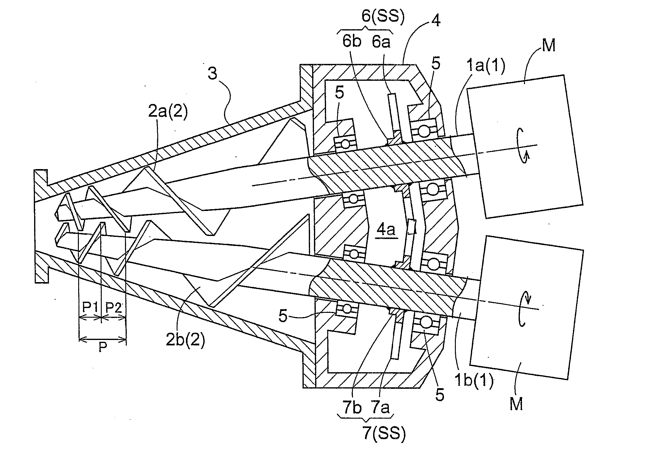
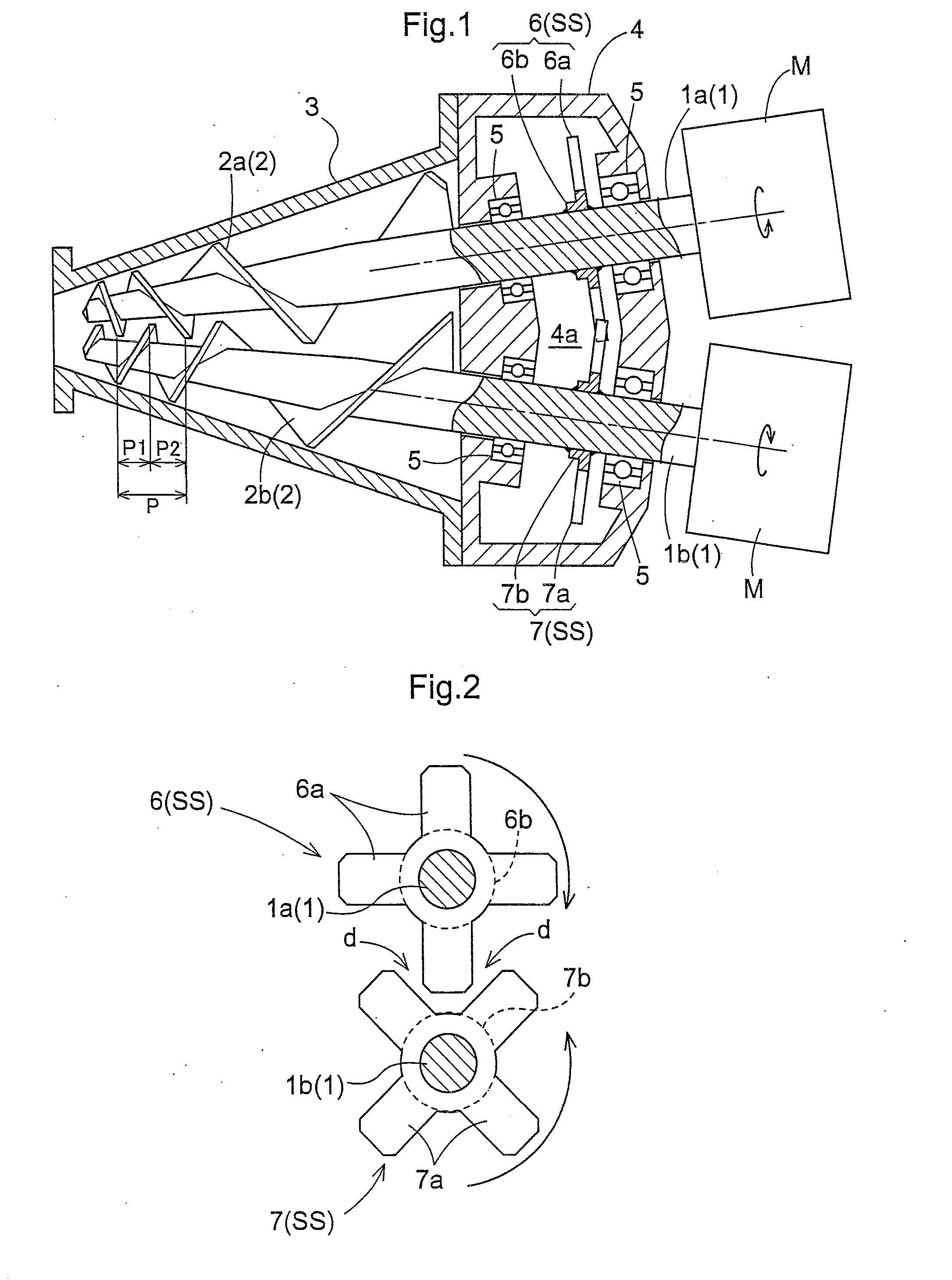
[0041]As shown in FIG. 1 and FIG. 2, a two-shaft extruder is for use in extruding an amount of high-viscosity substance such as un-formed rubber material, plastic material which has been kneaded by a kneading machine such as a mixer, a kneader, etc. The two-shaft extruder includes such components as a pair of rotor shafts 1 rotatably disposed with a distance therebetween diminishing toward the leading ends thereof, a pair of screw blades 2 mounted to the respective leading ends of the pair of rotor shafts 1, a pair of motors M with reduction mechanism provided at the respective base ends of the pair of rotor shafts 1 as a pair of drive units for rotatably driving the rotor shafts 1 respectively, and so on.

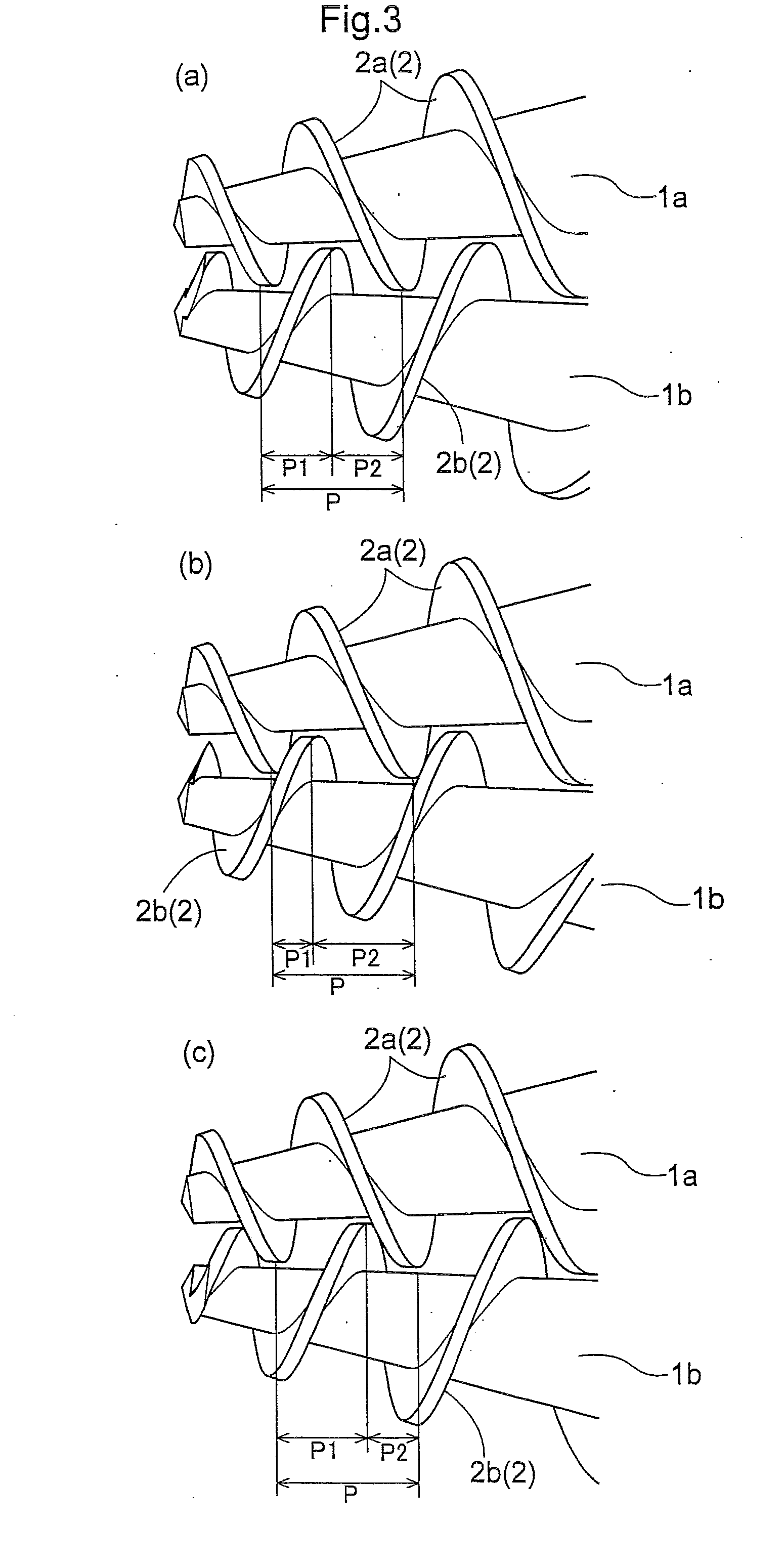
[0042]Each rotor shaft 1 has an approximately cylindrical shape with a tapered leading end. The screw blade 2 is configured as a variable pitch type having its pitch width P progressively decreasin...

second embodiment

[0052]In this embodiment, only differences thereof from the first embodiment will be discussed, with discussion of the identical parts and arrangements to those in the first embodiment being omitted.

[0053]Next, there will be described a screw blade contact preventing mechanism SS relating to the present invention.

[0054]As shown in FIG. 5 and FIG. 6, two sets of the first abutment members 6 and the second abutment members 7 are provided along the longitudinal direction of each rotor shaft 1 (that is, the direction along the bisector dividing the internal angle formed between the pair of rotor shafts 1 into two equal angles). And, the positions of projecting portions 6a1 of the first abutment member 6 belonging to the base end side set (outline portions in FIG. 6) and the positions of projecting portions 6a2 of the first abutment member 6 belonging to the leading end side set (shaded line portions in FIG. 6) adjacent to the base end side set are rendered different from each other in t...

third embodiment

[0057]In this embodiment, only differences thereof from the first embodiment will be discussed, with discussion of the identical parts and arrangements to those in the first embodiment being omitted.

[0058]Next, there will be described a screw blade contact preventing mechanism SS relating to the present invention.

[0059]As shown in FIG. 7 and FIG. 8, three sets of the first abutment members 6 and the second abutment members 7 are provided along the longitudinal direction of each rotor shaft 1. And, the positions of projecting portions 6a1 of the first abutment member 6 belonging to the base end side set (outline portions in FIG. 8) and the positions of projecting portions 6a2 of the first abutment member 6 belonging to the intermediate side set (shaded portions in FIG. 8) adjacent to the base end side set and the positions of projecting portions 6a3 of the first abutment member 6 belonging to the leading end side set (meshed portions in FIG. 8) adjacent to the intermediate side set a...


PUM

PropertyMeasurementUnit
Speedaaaaaaaaaa
Phaseaaaaaaaaaa

Abstract

In a two-shaft extruder, a pair of rotor shafts (1) is rotatably arranged such that the closer to the head end of the pair, the smaller the distance between the pair. The pair of rotor shafts (1) is respectively provided with screw blades (2) mounted on the head end side of the pair. The rotor shafts (1) are adapted such that one screw blade (2a) enters gaps of the other screw blade (2b). Drive devices (M) for rotationally driving the pair of rotor shafts (1) are mounted on the respective base ends of the pair. The extruder has a screw blade contact prevention mechanism (SS) which, when the pair of rotor shafts (1) is driven, prevents the pair from having a phase difference greater than a predetermined level.

Description

TECHNICAL FIELD[0001]The present invention relates to a two-shaft extruder comprising a pair of rotor shafts rotatably disposed with a distance therebetween diminishing toward the leading ends thereof, a screw blade mounted to the leading end of each one of the pair of rotor shafts, one screw blade intruding into the pitch of the other screw blade; and a drive unit mounted the base end of each one of the pair of rotor shafts for rotatably driving the rotor shaft associated therewith.BACKGROUND ART[0002]Such two-shaft extruder is configured to be capable of extruding an amount of high-viscosity substance such a un-formed rubber material, plastic material charged therein while kneading the substance with the screw blades.[0003]Conventionally, with a two-shaft extruder, in general, as shown in FIG. 9, a motor M with a reduction mechanism is mounted as a drive unit to the base end of one rotor shaft 1a alone. Whereas, a conical gear 15 is attached to each one of the pair of rotor shafts...

Claims


Application Information

Patent Timeline
IPC IPC(8): B29C47/40B29C47/08B29C48/525B29C48/92
CPCB29C47/0801B29C47/402B29C47/6012B29C47/92B29C47/0009B29C47/0803B29C2947/92952B29C2947/92095B29C2947/9239B29C2947/92571B29C2947/9259B29C2947/92885B29C2947/92076B29B7/484B29B7/489B29B7/728B29B7/7495B29C48/402B29C48/92B29C48/252B29C48/03B29C48/2522B29C2948/9239B29C2948/9259B29C2948/92076B29C2948/92095B29C2948/92571B29C2948/92885B29C2948/92952B29B7/488B29C48/525B29B7/60
Inventor SAIUCHI, SHIGETOIRIE, MAKOTO
Owner MORIYAMA
Why Eureka
Try Eureka