Equipment for cleaning sizing agent on surface of fabric

A technology for cleaning equipment and slurry, which is used in fabric surface trimming, textile material carrier treatment, and spraying/jetting textile material processing. Kneading effect, simple structure, good cleaning effect

Inactive Publication Date: 2017-09-29
CHANGXING JIAPU YIHANG TEXTILE FACTORY
View PDF1 Cites 6 Cited by
  • Summary
  • Abstract
  • Description
  • Claims
  • Application Information

AI Technical Summary

Problems solved by technology

[0004] The purpose of the present invention is to address the deficiencies of the prior art, by arranging a roller that can push the cloth to move and two rollers that can be opened to both sides to rub the transported cloth and spray the cloth after the rubbing is completed. Water cleaning thus overcomes the problems of incomplete cleaning, low cleaning efficiency and large amount of water resources used when cleaning the surface of the fabric with residual slurry

Method used


Image

  • Equipment for cleaning sizing agent on surface of fabric
  • Equipment for cleaning sizing agent on surface of fabric
  • Equipment for cleaning sizing agent on surface of fabric

Examples


Embodiment 1

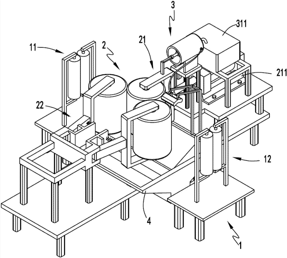
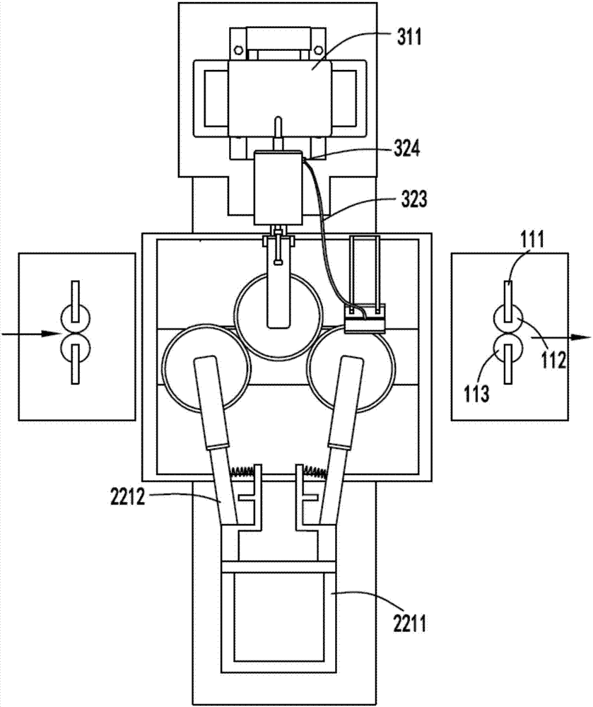
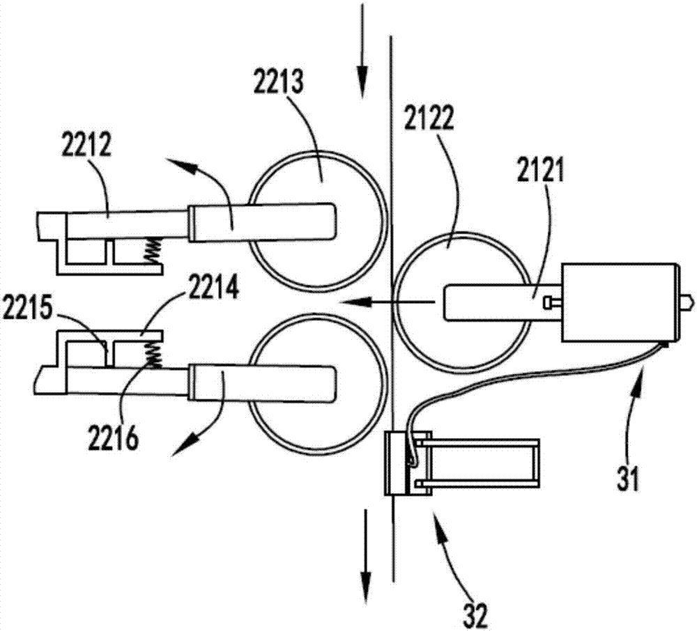
[0035] Such as figure 1 , figure 2 , image 3 , Figure 4 , Figure 5 , Figure 6 and Figure 7 As shown, a fabric surface slurry cleaning equipment includes a conduction part 1, the conduction part 1 includes an introduction device 11 and an export device 12 for conducting textile fibers; a rubbing part 2, and the rubbing part 2 is arranged on the introduction device 11 and the exporting device 12, the rubbing part 2 includes a pushing mechanism 21 and a rolling mechanism 22 respectively arranged on both sides of the textile fiber in the transmission process, and the pushing mechanism 21 is used to push the textile fiber toward the rolling mechanism 22. Direction movement, the rolling mechanism 22 is used to cooperate with the pushing mechanism 21 to roll the surface of the textile fiber synchronously forward and backward; the cleaning part 3, the cleaning part 3 includes a water supply device arranged above the pushing mechanism 21 The mechanism 31 and the spraying me...

Embodiment 2

[0049] Such as figure 1 , figure 2 , image 3 , Figure 4 , Figure 5 , Figure 6 and Figure 7 As shown, the components that are the same as or corresponding to those in the first embodiment are marked with the corresponding reference numerals in the first embodiment. For the sake of simplicity, only the differences from the first embodiment will be described below. The difference between the second embodiment and the first embodiment is that: the spraying member 322 is set in an inverted V shape, and several spray holes 3221 are opened on the V-shaped surface of the spraying member 322;

[0050] On the one hand, this kind of setting makes it possible to spray water on the front and rear sides of the cloth through a spraying member 322. In addition, because of its inverted V-shaped setting, it also makes it possible to say that the jets are sprayed obliquely from one side of the cloth. onto the fabric for better cleaning results.

[0051] Working process: the cloth is...


PUM


Abstract

The invention relates to a fabric surface slurry cleaning equipment, comprising a conduction part, the conduction part includes an introduction device and an outlet device for conducting textile fibers; a kneading part, the kneading part is arranged between the introduction device and the outlet device, the kneading part includes The pushing mechanism and the rolling mechanism respectively arranged on both sides of the textile fiber during the transmission process, the pushing mechanism is used to push the textile fiber to move towards the direction of the rolling mechanism, and the rolling mechanism is used to cooperate with the pushing mechanism to move forward and backward simultaneously The surface of the textile fiber is rolled in the direction; the cleaning part, the cleaning part includes a water supply mechanism set above the pushing mechanism and a water supply mechanism set on the side of the rolling mechanism for spraying the water in the water supply mechanism to the rolled textile fiber The spray mechanism on the surface; the present invention overcomes the problems of incomplete cleaning, low cleaning efficiency and large amount of water resources used when cleaning the surface of the fabric with residual slurry.

Description

technical field [0001] The invention relates to the technical field of fabric post-processing equipment, in particular to a fabric surface slurry cleaning equipment. Background technique [0002] Various textile products continue to appear in the existing market and are applied to various clothing fabrics. Another pollution process of fabric production is the finishing stage. This stage is very polluting to fabrics and the environment. Traditional fabrics are in this process. A large number of various additives are used. Although the surface of the fabric has been improved, a large amount of pollutants are produced and the residues will cause discomfort and allergies to the human skin, and also kill the active ingredients of many natural materials. Wearing Or use is all unsatisfactory to playing the service life of health care skin and prolonging clothes. [0003] Authorized notification number CN201620482682.9 is a Chinese utility model patent, which discloses a fabric was...

Claims


Application Information

Patent Timeline
Patent Type & Authority Applications(China)
IPC IPC(8): D06B1/02D06B23/04D06C19/00
CPCD06B1/02D06B23/04D06C19/00
Inventor 嵅奇
Owner CHANGXING JIAPU YIHANG TEXTILE FACTORY
Why Eureka
Try Eureka