
Apparatus for producing multilayer sheet and method of producing the multilayer sheet

a production method and multi-layer technology, applied in the direction of fixed capacitor details, capacitor manufacture, fixed capacitors, etc., can solve the problems of high equipment cost and running cost, and the conventional production technique of multi-layer sheets requires a lot of time and labor, and achieves excellent productivity and low cost.

Inactive Publication Date: 2011-04-21
KOJIMA PRESS IND CO LTD +1
View PDF3 Cites 4 Cited by
  • Summary
  • Abstract
  • Description
  • Claims
  • Application Information

AI Technical Summary

Benefits of technology

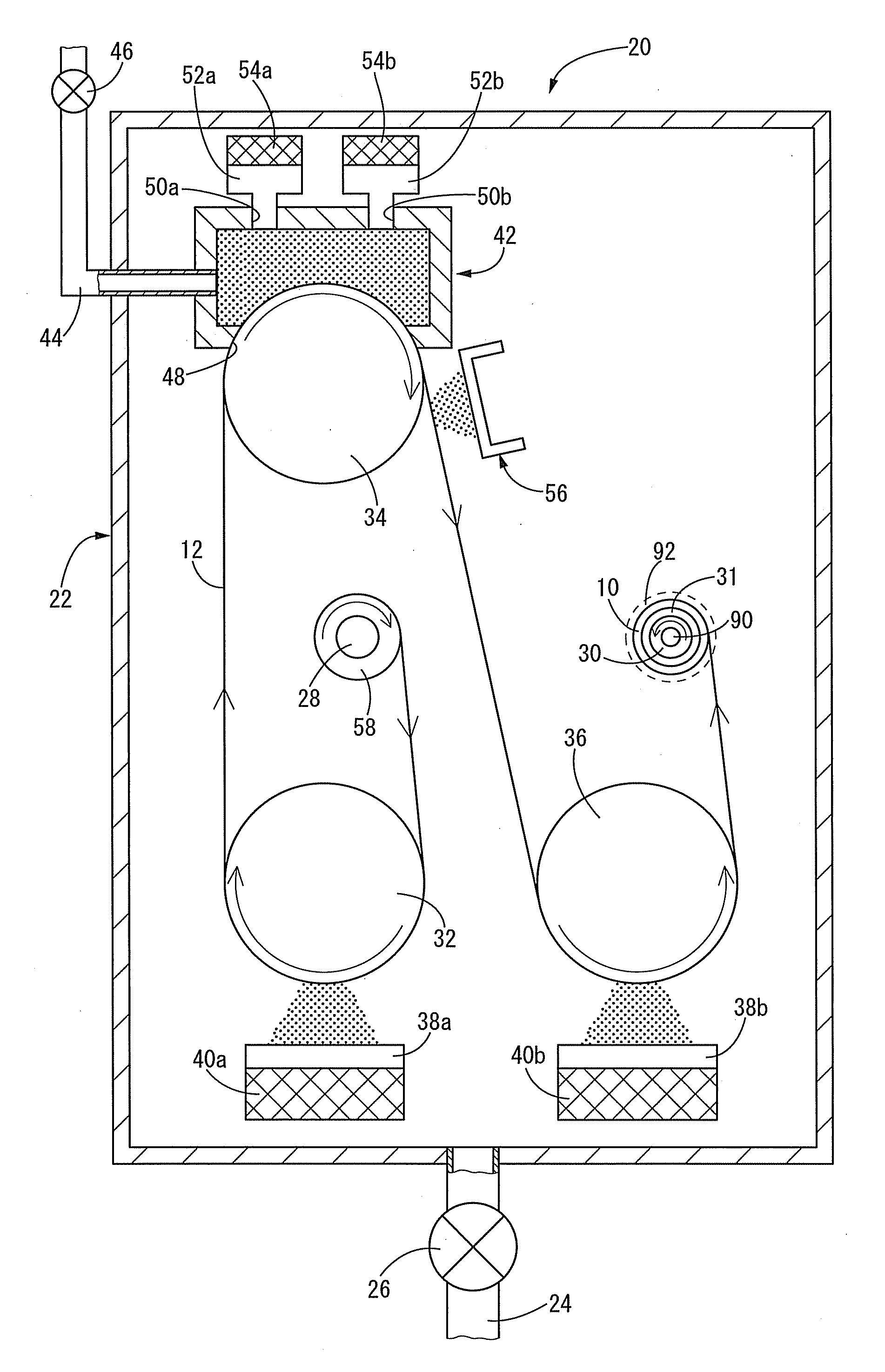
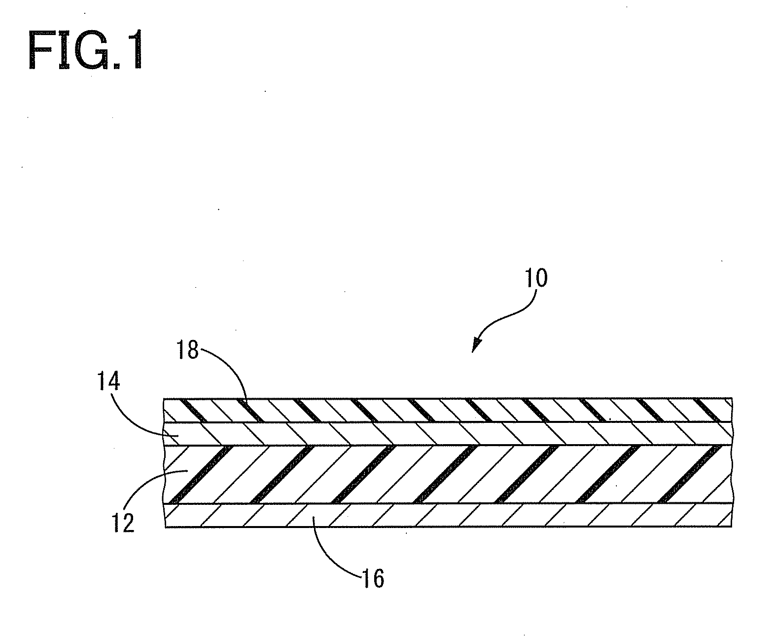
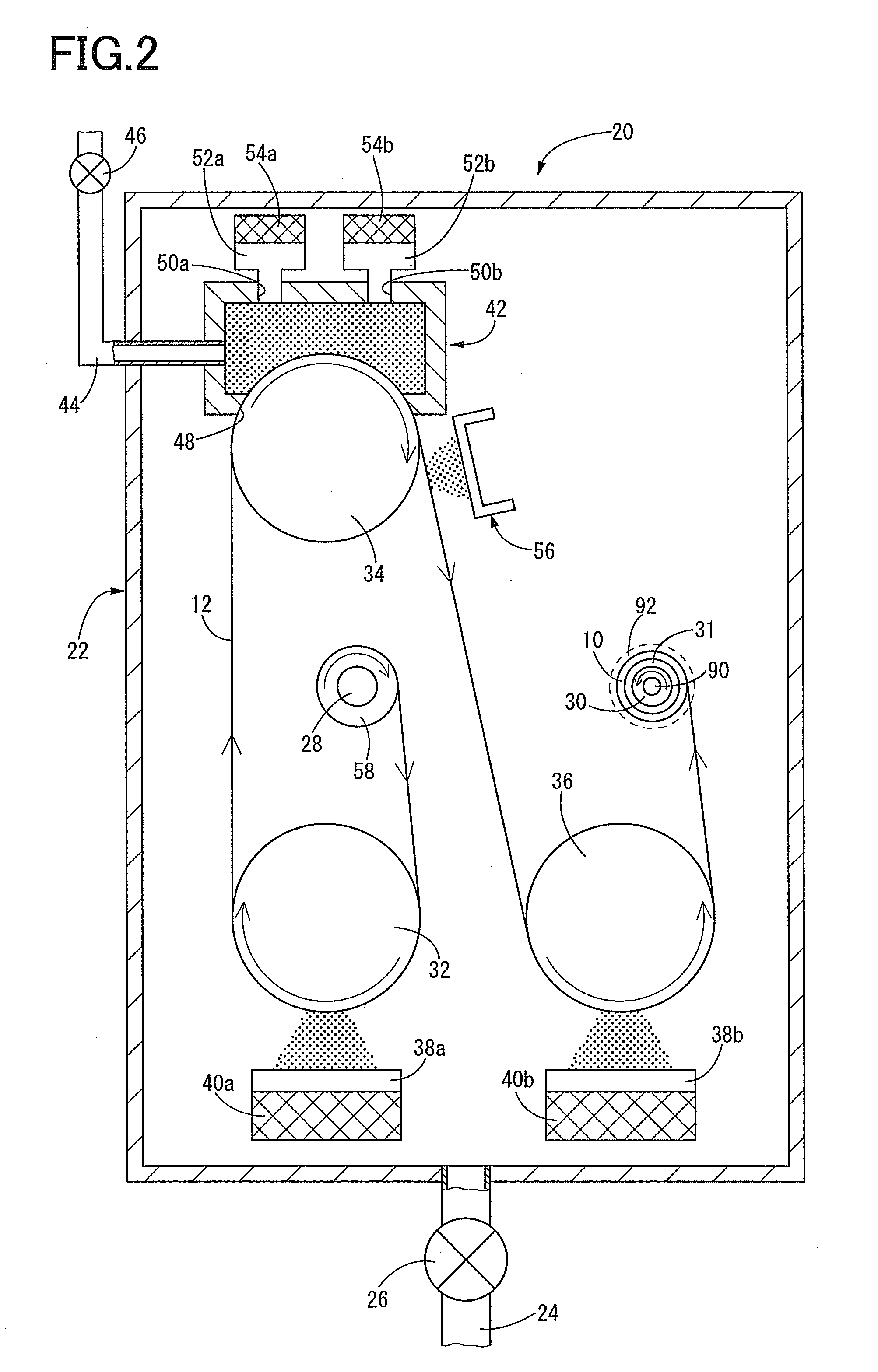
[0009]The present invention has been made in the light of the situations described above, and an object of the invention is to provide an apparatus for producing a multilayer sheet including a resin film, a vapor-deposited metal film formed on both surfaces of the resin film, and a vapor-deposited polymer film formed on at least one of the vapor-deposited metal film, at a sufficiently low cost and with excellent productivity, and it is another object of the invention to provide a method of producing the multilayer sheet.
[0038]Consequently, when the apparatus for producing a multilayer sheet according to the present invention is used, there is no need to provide a continuous vacuum vapor deposition apparatus for forming a vapor-deposited metal film and a roll-to-roll vacuum deposition polymerization apparatus for forming a vapor-deposited polymer film, separately. Further, there is no need to set the metallized film on the roll-to-roll vacuum deposition polymerization apparatus after the metallized film constituted of a resin film and vapor-deposited metal films formed on respective surfaces of the resin film are removed from the continuous vacuum vapor deposition apparatus. Further, there is no need to control the pressure in the apparatuses separately so as to be in a vacuum state or an open-to-air condition in the above operation, which is troublesome and time-consuming operation.
[0039]Therefore, the apparatus for producing a multilayer sheet of the present invention can advantageously form a multilayer sheet including a vapor-deposited metal film formed on both surfaces of the resin film and a vapor-deposited polymer film formed on at least one surface of the vapor-deposited metal film, at a sufficiently low cost and with excellent productivity.

Problems solved by technology

At this time, the inside of the continuous vacuum deposition apparatus should be changed to an open-to-air condition from a vacuum condition, and the inside of the roll-to-roll vacuum deposition polymerization apparatus should be changed to a vacuum condition from an open-to-air condition, which is troublesome.
Therefore, the conventional production technique of multilayer sheet requires not only high equipment cost and running cost, but also requires operations that involve a lot of time and labor.

Method used


Image

  • Apparatus for producing multilayer sheet and method of producing the multilayer sheet
  • Apparatus for producing multilayer sheet and method of producing the multilayer sheet
  • Apparatus for producing multilayer sheet and method of producing the multilayer sheet

Examples


first embodiment

[0091]The film-forming apparatus 62 of the present embodiment includes a fourth roller 64, in addition to the first to third rollers 32, 34 and 36, in the vacuum chamber 22 of the apparatus 20 according to the The fourth roller 64 has the same outer diameter as the first to third rollers 32, 34 and 36. The fourth roller 64 is disposed in the vacuum chamber 22 at a position opposite to the third roller 36 in the longitudinal direction of the vacuum chamber 22 with the take up roller 30 disposed therebetween.

[0092]Further, a second auxiliary vacuum chamber 66 is disposed at a position opposite to the take up roller 30 with the fourth roller 64 interposed therebetween. To the second auxiliary vacuum chamber 66, a second auxiliary exhaust pipe 68 that extends from the outside of the vacuum chamber 22 through a side wall of the vacuum chamber 22 is connected. Further, a second auxiliary vacuum pump 70 is connected to the second auxiliary exhaust pipe 68 at a protruding portion thereof w...

second embodiment

[0119]In the second embodiment, the first auxiliary vacuum chamber 42 and the second auxiliary vacuum chamber 66 are separately constituted. Further, the first auxiliary vacuum pump 46 and the second auxiliary vacuum pump 70 are separately constituted. However, the first auxiliary vacuum chamber 42 and the second auxiliary vacuum chamber 66 may be constituted by one auxiliary vacuum chamber, and the first auxiliary vacuum pump 46 and the second auxiliary vacuum pump 70 may be constituted by one auxiliary vacuum pump. In this case, a part of the second roller 34 and a part of the fourth roller 64 are disposed so as to be exposed to the inside of the one auxiliary vacuum chamber. In the one auxiliary vacuum chamber, the first dielectric film 18 and the second dielectric film 19 are formed on the first electrode film 14 and the second electrode film 16, respectively.

[0120]In addition, the present invention is also advantageously applicable to an apparatus for producing a multilayer she...


PUM

PropertyMeasurementUnit
Thicknessaaaaaaaaaa
Dielectric constantaaaaaaaaaa

Abstract

An apparatus for producing a multilayer sheet including a resin film, a vapor-deposited metal film and a vapor-deposited polymer film at a low cost and with excellent productivity is provided which comprises: a vacuum chamber which is made to be in a vacuum state by exhaust means; a feeding roller; a take up roller; a first to third rollers, first metal vapor deposition means for forming a first vapor-deposited metal film on one surface of a resin film at a periphery of the first roller; vapor deposition polymerization means for forming a vapor-deposited polymer film on the first vapor-deposited metal film by vapor deposition polymerization at a periphery of the second roller; and second metal vapor deposition means for forming the second vapor-deposited metal film on the other surface of the resin film at a periphery of the third roller.

Description

[0001]The present application is based on Japanese Patent Application No. 2009-238178 filed on Oct. 15, 2009, the contents of which are incorporated herein by reference.BACKGROUND OF THE INVENTION[0002]1. Field of the Invention[0003]The present invention relates to an apparatus for producing a multilayer sheet and a method of producing the multilayer sheet. More particularly, the present invention relates to a novel apparatus for producing a multilayer sheet by forming a vapor-deposited metal film on both surfaces of a resin film, and forming a vapor-deposited polymer film on at least one of the vapor-deposited metal films, and the present invention also relates to a method of producing such a multilayer sheet.[0004]2. Discussion of Related Art[0005]Conventionally, a multilayer sheet is used in a wide variety of applications, which is obtained by forming a vapor-deposited metal film on both surfaces of a resin film, and forming a vapor-deposited polymer film on at least one of the v...

Claims


Application Information

Patent Timeline
IPC IPC(8): H05H1/24C23C14/14C23C14/06C23C14/20C23C14/56H01G4/015H01G4/18
CPCB05D1/60B05D7/52C23C14/20H01G13/00H01G4/008H01G4/145H01G4/33C23C14/562
Inventor ITO, KAORUNOGUCHI, MASUMITANAKA, HIDEAKIIKEDASHIMOMURA, MAKOTOTADA, ISAOHAYASHI, NOBUHIROIRIKURA, HAGANE
Owner KOJIMA PRESS IND CO LTD
Learn More