System and method of using a compressed air storage system with a gas turbine

a technology of compressed air and storage system, which is applied in the direction of electrical storage system, electric generator control, forging/pressing/hammering apparatus, etc., can solve the problems of low overall efficiency, low energy value and availability of above-ground systems, and high cost of above-ground systems

Active Publication Date: 2011-04-28
NUOVO PIGNONE TECH SRL
View PDF19 Cites 100 Cited by
  • Summary
  • Abstract
  • Description
  • Claims
  • Application Information

AI Technical Summary

Problems solved by technology

However, above-ground systems tend to be expensive and typically do not have a storage capacity comparable to an underground cavern—though they can be attractive in that they can be sited in areas where underground formations are not available.
Thus, in a diabatic-CAES system, although the heat of compression may be largely present when entering the cavern, its energetic value and availability is diminished as it mixes with the cavern air and as it further cools to surrounding or ambient temperature during storage—leading to a low overall efficiency.
However, overall system efficiency is not necessarily the guiding parameter for determining whether to build or operate a compressed air energy storage system.
And, another factor to consider in whether to build a compressed air energy storage system is capital expenditure.
Because of an increased power surge capability provided by such a compressed air storage system, that capability may obviate the need to build additional and expensive conventional power generation capacity such as natural gas or coal-fired power plants.
However, construction of such standalone compressed air energy storage systems itself typically includes an initial capital expenditure that may not be justified, despite the ability to collect and store low-cost energy and sell the stored energy during times of peak demand.
Thus, in some markets where there is a need for power surge capability, where there is surplus evening capacity, or where renewable energy sources are available, power producers may nevertheless elect not to build such a system because the initial costs of construction are too high.
However, such systems cannot typically benefit from or consume renewable energy resources and do not typically have an energy storage capability, aside from their primary power supply of natural gas.
Thus, to meet total power capacity demands of a given area or market, and because of the aforementioned high cost of constructing a compressed air energy storage system, power providers may elect to construct power systems that are based only on natural gas-powered systems.
Thus, because of initial high cost of construction, power providers may be failing to take advantage of a renewable source that is readily available.

Method used


Image

  • System and method of using a compressed air storage system with a gas turbine
  • System and method of using a compressed air storage system with a gas turbine
  • System and method of using a compressed air storage system with a gas turbine

Examples


Embodiment Construction

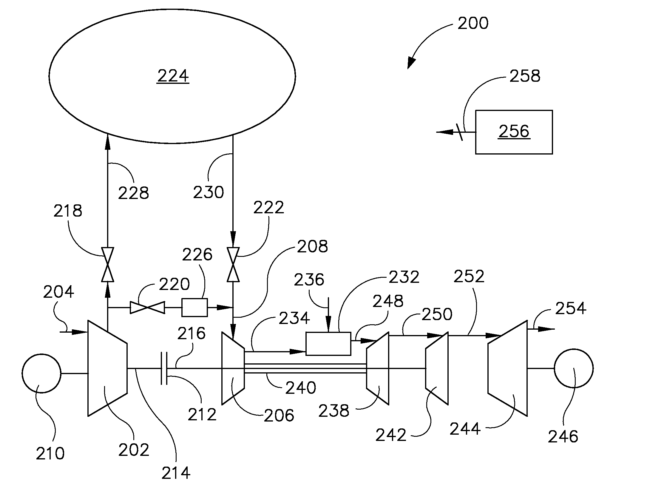
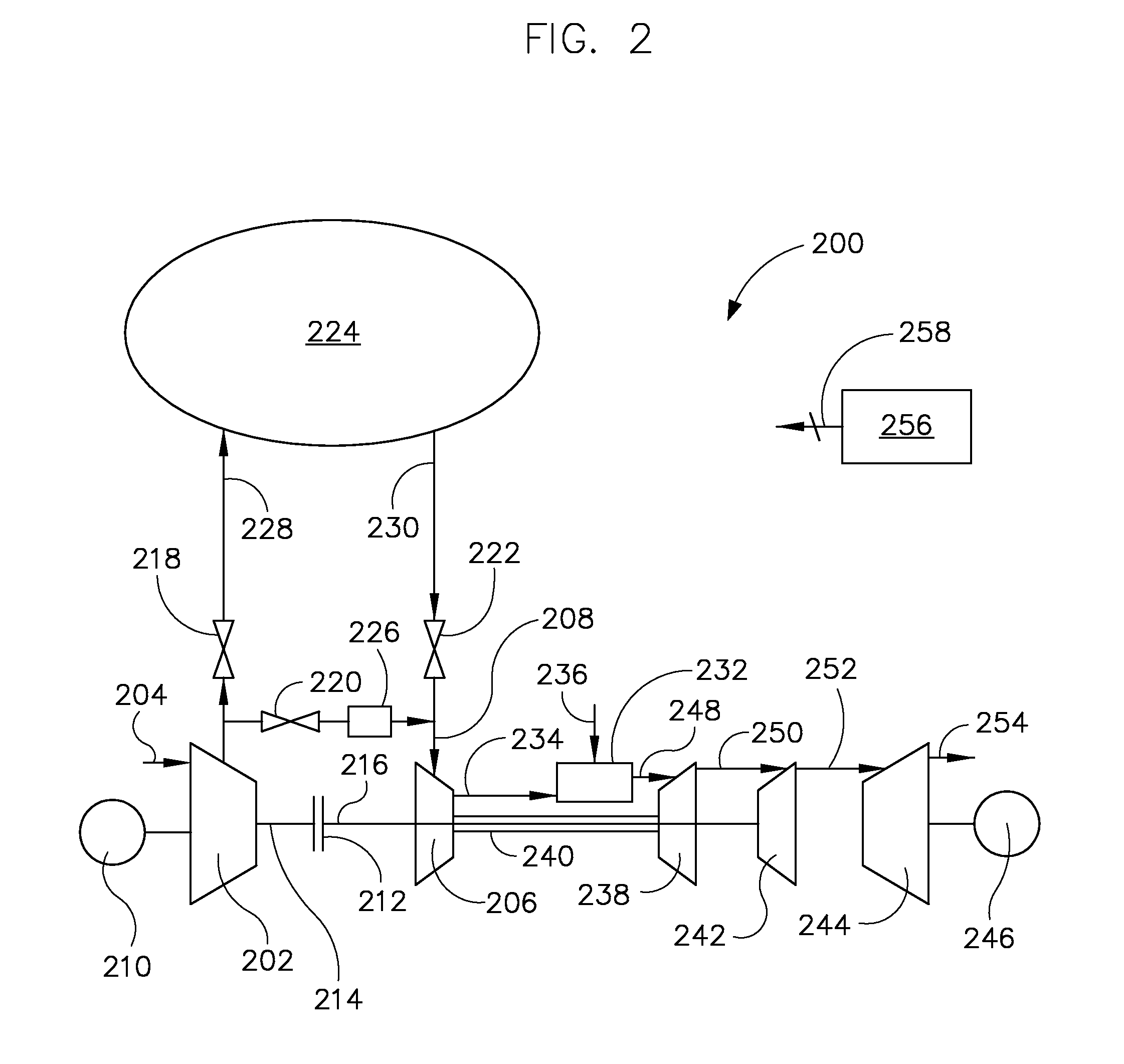
[0022]According to embodiments of the invention, a system and a method of operating the system are provided that stores energy from a first compressor in a cavern and directs compressed air from the first compressor to a second compressor in a natural gas-fired turbine system for producing electrical energy. The system and method of operating the system further include modifying a natural gas fired turbine to enable using a compressor in the turbine to compress air alternately for powering the turbine and for storage in an air cavern.

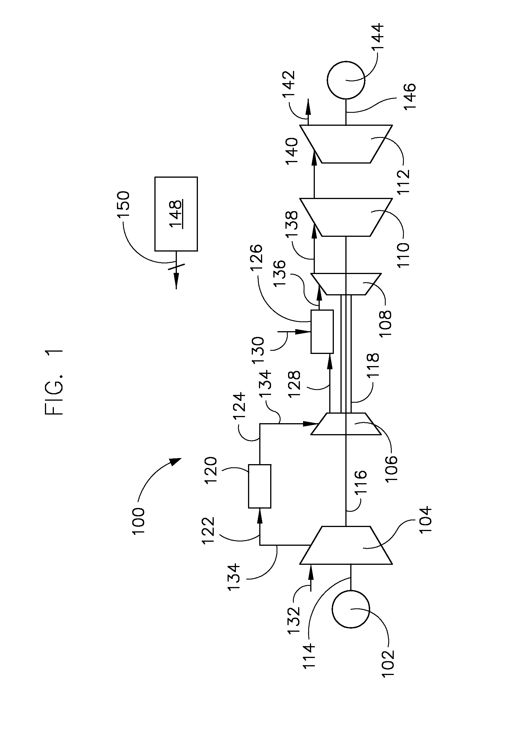
[0023]FIG. 1 illustrates components of a typical natural gas turbine 100 that may incorporate embodiments of the invention, or that may be modified according to embodiments of the invention. Gas turbine 100 includes a first motor / generator 102 coupled to a first compressor 104, a second compressor 106, a first turbine 108, a second turbine 110, and a power turbine 112. First motor / generator 102 is coupled to first compressor 104 via a shaft 114, and may...


PUM

PropertyMeasurementUnit
temperatureaaaaaaaaaa
timeaaaaaaaaaa

Abstract

A power generation system includes a first compressor, a second compressor, a combustor configured to receive compressed air from the second compressor to produce an exhaust stream, a first turbine, and a power turbine. The first turbine is configured to receive the exhaust stream, generate a rotational power from the exhaust stream, output the rotational power to a second compressor, and output the exhaust stream. The system includes a coupling device configured to couple and decouple the first compressor to / from a second turbine, an electrical generator coupled to an output of the power turbine and configured to output electrical power, and a controller configured to cause the coupling device to mechanically decouple the second turbine from the first compressor, and cause the coupling device to direct compressed air from an air storage cavern to an inlet of the second compressor.

Description

BACKGROUND OF THE INVENTION[0001]Embodiments of the invention relate generally to compressed air storage systems and, more particularly, to a system and method of using a compressed air storage system with a gas turbine.[0002]Types of compressed air energy storage systems include diabatic compressed air energy storage (diabatic-CAES) systems and adiabatic compressed air energy storage (ACAES) systems. Such systems typically include a compression train having one or more compressors that operate during a compression stage to compress intake air to 80 bars or more, where the energy stored is available to later power a turbine to generate electricity. Typically, the compressed air can be stored in several types of underground media that include but are not limited to porous rock formations, depleted natural gas / oil fields, and caverns in salt or rock formations. Alternatively, the compressed air can be stored in above-ground systems such as, for example, high pressure pipelines similar...

Claims


Application Information

Patent Timeline
Patent Type & Authority Applications(United States)
IPC IPC(8): F02C6/00F02C3/04B23P11/00
CPCF02C6/16F02C7/10Y10T29/4932Y02E60/15F05D2260/42H02J15/006Y02E60/16
Inventor FINKENRATH, MATTHIASNAIDU, BALACHANDARBOOTH, CHARLES MICHAELFERGUSON, GARLANDHOFFMANN, STEPHANIE MARIE-NOELLEFREUND, SEBASTIAN W.
Owner NUOVO PIGNONE TECH SRL
Why Eureka
Try Eureka