
Stack axle assembly and transporters having the same

a technology of axle assembly and transporter, which is applied in the field of transporter, can solve the problems of not being able to engage and move the cask out of the fuel building(s), all options have significant disadvantages, and require an extended operating space for heavy multi-axle specialized carrier trailers, etc., and achieves the effects of reducing the time and effort to engage and disengage the cask, increasing the functionality of the system, and increasing safety

Inactive Publication Date: 2011-04-28
INTELLIPORT CORP
View PDF10 Cites 20 Cited by
  • Summary
  • Abstract
  • Description
  • Claims
  • Application Information

AI Technical Summary

Benefits of technology

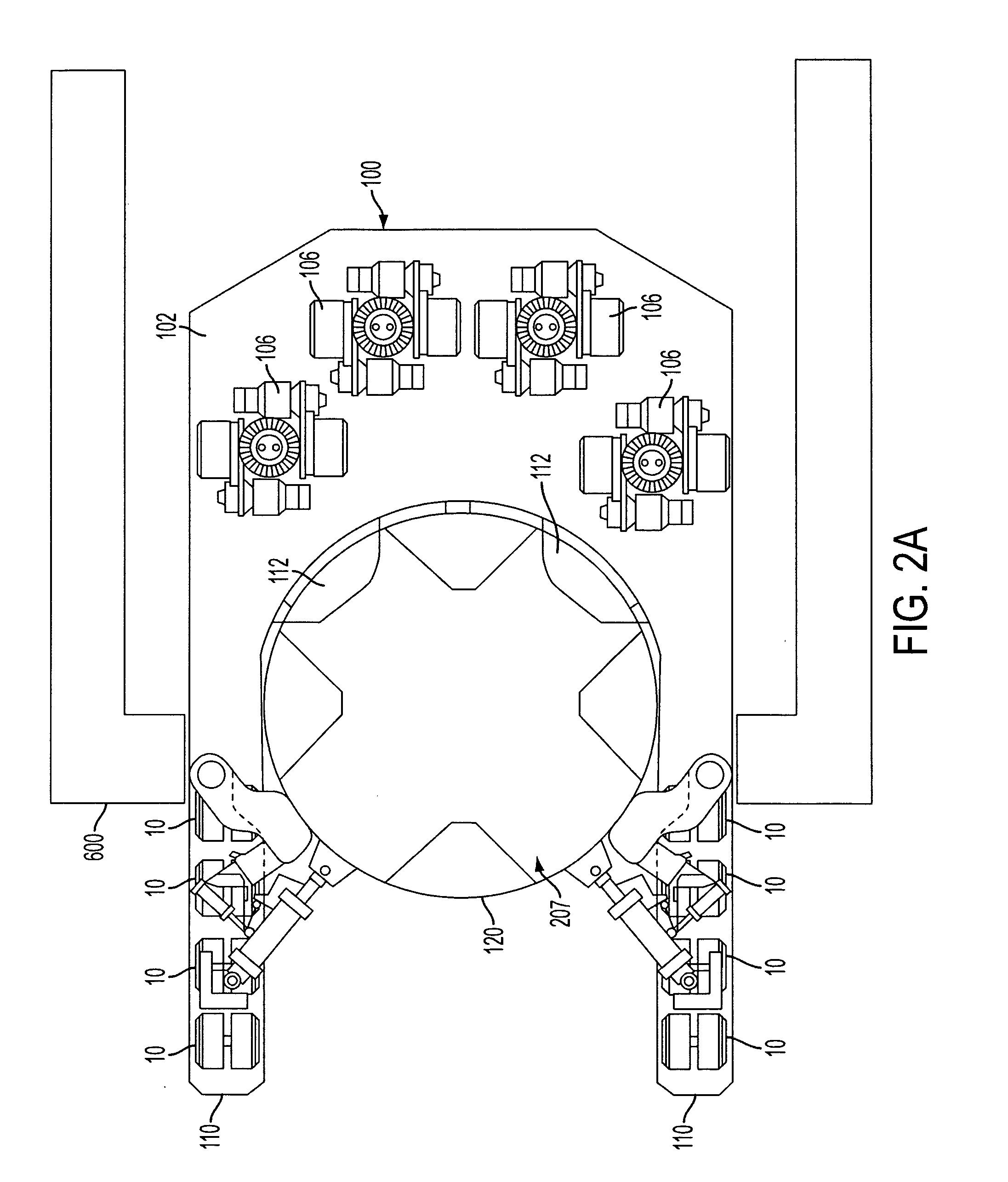
[0020]It is a further aspect of the present invention to provide rigidly fixed and forward extended pawls at the aft base of a U-shaped cask transporter which will engage two or more of the air vents in the bottom of the casks, while two clamps located high on the transporters arms extend and lock to bear solidly against the forward sides of the cask, locking the cask into the transporter and holding it in the upright position without possibility of tipping forward. In addition, two self-locking toggle clamps provide backup support in the event of a main clamp failure.
[0021]This engagement means the time and effort to engage and disengage from the casks are dramatically reduced. Also safety is greatly increased by not requiring workmen to climb up high on top of the cask to position and attach the heavy lifting gear as is currently necessary with the crawler mounted gantries.
[0022]The narrow shape and omni-directional effortless maneuverability of the stack axle cask transporter dramatically increases the functionality of the system, particularly when placing casks in the narrow confines of the ISFSI storage pads. Those two factors, narrow shape and omni-directional maneuverability allow casks to be placed closer together, and thereby reduce the acreage required for a new or expanded ISFSI storage facility, which is an important factor for nuclear plants that have limited space.
[0024]According to the present invention, the self-propelled stack axle cask transporter engages and lifts the casks off the floor from inside the fuel building and is driven directly to the final ISFSI storage pad location. The stack axle cask transporter's narrow shape and omni directional travel capability allows new or expanded ISFSI storage pads to have much narrowed alleys between single and double rows of stored casks. With its omni directional travel capability, the stack axle transporter can rotate on-center and provide infinitely accurate maneuvers in linear, lateral, or diagonal travel patterns to allow effortless precision placement of casks in tight, and otherwise difficult to access, storage locations.
[0032]In the cask transporter, the load relief controller may decrease fluid pressure to the cylinder housing of selected single or pairs of axle assemblies to transfer their load onto surrounding fully pressurized cylinder housings in event of any single axle assembly malfunction.

Problems solved by technology

These options all have significant disadvantages.
For example, for vertical-type casks, heavy multi axle specialized carrier trailers require an extended operating space and are not capable of engaging and moving the casks out of the fuel building(s), or of doing the actual positioning the cask in the close spacing requirements within the ISFSI.
Furthermore, a disadvantage of air cushion devices is that they require a large pressurized air supply and a smooth, non-porous surface in order to maintain lift and operate properly.
Moreover, specialized vertical lift gantry frames attached to crawler tractor bed assemblies have the disadvantage of a large size, especially height, and a lack of maneuverability.
The crawler treads tend damage operating surfaces when skid turning under these types of loading conditions.
However, in vertical-type spent nuclear fuel cask applications, existing IP-SPMT devices are not sufficient because of the need to pick and place the vertical cask directly to or from the operating surface.

Method used


Image

  • Stack axle assembly and transporters having the same
  • Stack axle assembly and transporters having the same
  • Stack axle assembly and transporters having the same

Examples


Embodiment Construction

[0051]Reference will now be made in detail to the embodiments of the present invention, examples of which are illustrated in the accompanying drawings, wherein like reference numerals refer to the like elements throughout.

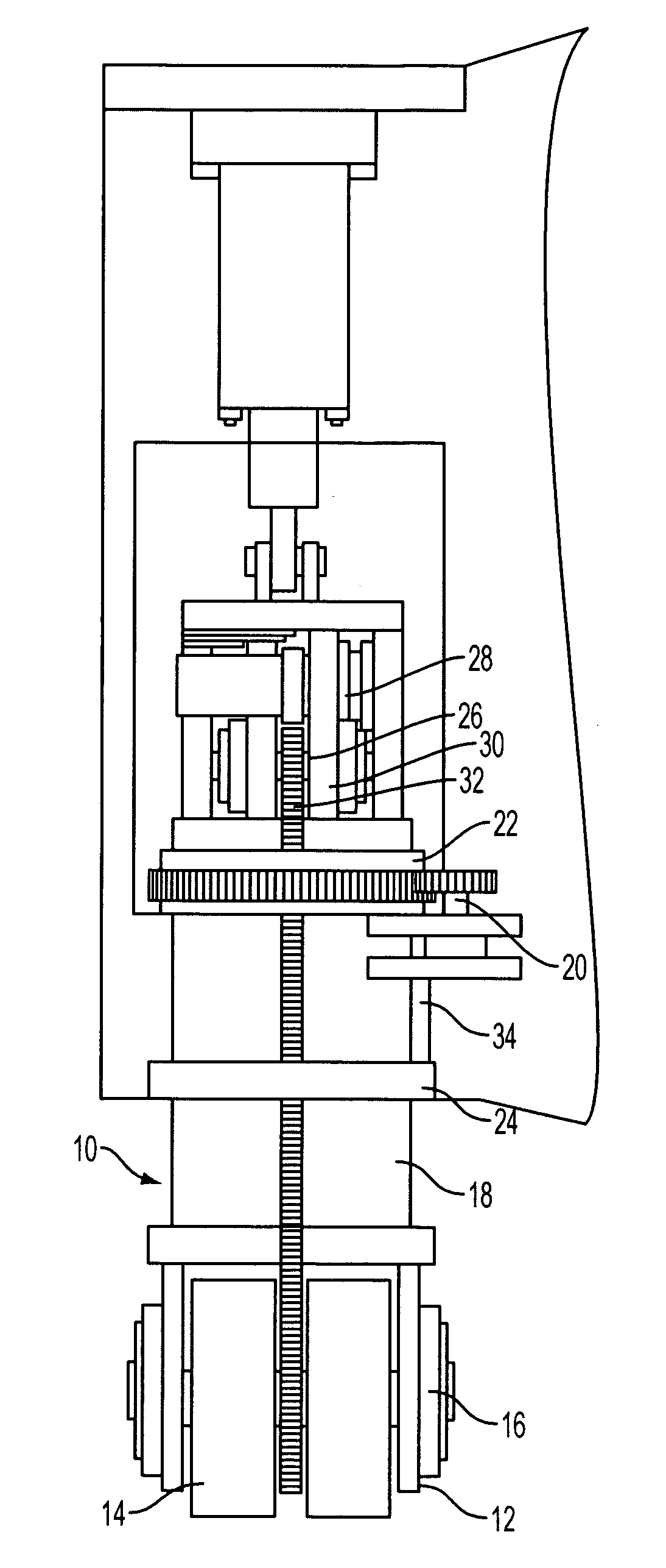
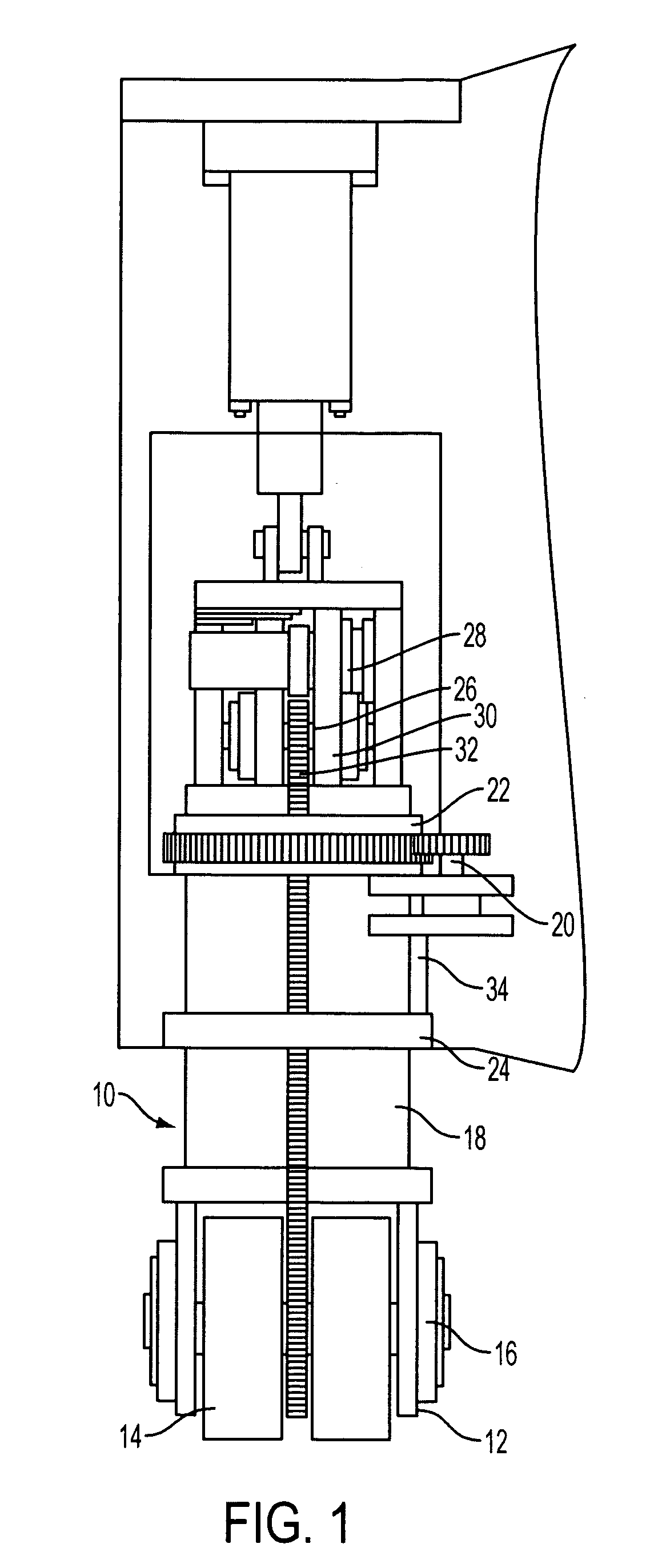
[0052]FIG. 1 shows an stack axle assembly 10 according to the present invention that allows self-propelled, omni directional travel in a heavy load transporter, where each “single wheel” is actually an independent driver wheel 12 and idler wheel 14 revolving on a common shaft / trunnion assembly 16, which is in turn attached to a open-center vertical rising cylinder 18 retained in a slew gear 20, upper bearing 22 and lower bearing 24. On the top of said vertical rising cylinder 18 is a frame assembly 26 in which a drive motor 28 connects an upper drive assembly 30 downwardly to a lower driven assembly 32 mounted between the idler wheel 14 and driver wheel 12. Although one drive motor 28 is shown, more than one drive motor may be employed with the present invention. R...


PUM


Abstract

A stack axle assembly as used in a cask transporter or an horizontal storage module (HSM) gantry transporter. The stack axle assemblies include a slew gear; an upper bearing; a lower bearing; a vertical cylinder retained by the slew gear, upper bearing and lower bearing; an independent driver wheel and idler wheel revolving on a common shaft / trunnion assembly attached to the bottom of the vertical cylinder; a frame assembly formed on top of the vertical cylinder, the frame assembly including one or more drive motors connecting an upper drive assembly downwardly to a driven assembly mounted between the idler wheel and driver wheel; and a slew driver motor to drive the slew gear.

Description

BACKGROUND OF THE INVENTION[0001]1. Field of the Invention[0002]The present invention relates to a transporter to carry very heavy loads. More particularly, the present invention relates to a transporter with single wheel power driven axle assemblies that have omni-directional steering, fluid equalizing suspension, and on-center axle rotation capability in order to carry very heavy loads.[0003]2. Description of the Related Art[0004]A nuclear reactor operates by facilitating a controlled nuclear chain reaction in a reactor core. Typically, the nuclear reaction is fueled by an isotope of uranium, which is supplied to the reactor core in a plurality of elongated fuel rods, which are typically metallic structures that are packed with uranium pellets.[0005]When the fuel rods must be removed and replaced, the spent nuclear fuel is typically temporarily stored in water pools that dissipate generated thermal energy and attenuates radiation emitted from the spent nuclear fuel. For long-term ...

Claims


Application Information

Patent Timeline
Patent Type & Authority Applications(United States)
IPC IPC(8): B60K17/30B60B35/00
CPCB60K7/0007G21F5/14B60Y2200/41
Inventor TERRY, MELVIN DEAN
Owner INTELLIPORT CORP
Learn More