
Optical detection of planarization, breakthrough and end-point in membrane-mediated electropolishing of metal layers

Inactive Publication Date: 2011-04-28
EI DU PONT DE NEMOURS & CO
View PDF5 Cites 3 Cited by
  • Summary
  • Abstract
  • Description
  • Claims
  • Application Information

AI Technical Summary

Problems solved by technology

In CMP the surface of the wafer is continuously flooded by a polishing slurry containing suspended colloidal particles that scatter light and complicate optical measurements.
Consequently, optical measurements can be difficult to carry out without significant modifications of the polishing pad and the platen that supports the pad.
These methods vary in sensitivity and reliability and in the cost and complexity they contribute to the equipment.
However, the method is highly intrusive, requiring process compromises or extensive hardware modifications.” Such modifications are described in U.S. Pat. No. 5,893,796; U.S. Pat. No. 5,964,643; U.S. Pat. No. 6,045,439; U.S. Pat. No. 6,280,290; and U.S. Pat. No. 6,454,630.

Method used


Image

  • Optical detection of planarization, breakthrough and end-point in membrane-mediated electropolishing of metal layers
  • Optical detection of planarization, breakthrough and end-point in membrane-mediated electropolishing of metal layers
  • Optical detection of planarization, breakthrough and end-point in membrane-mediated electropolishing of metal layers

Examples


Embodiment Construction

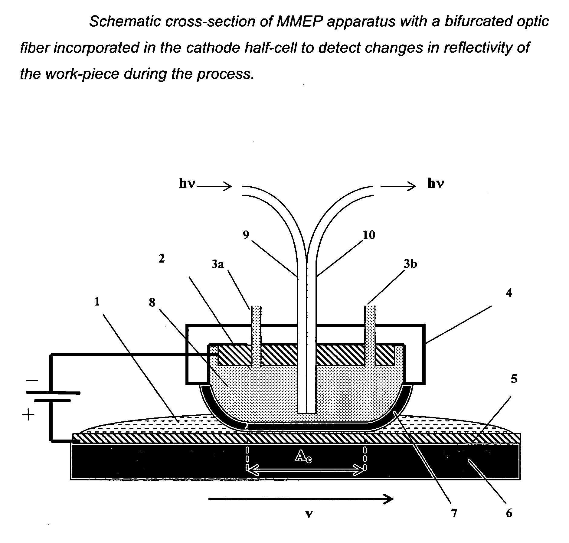
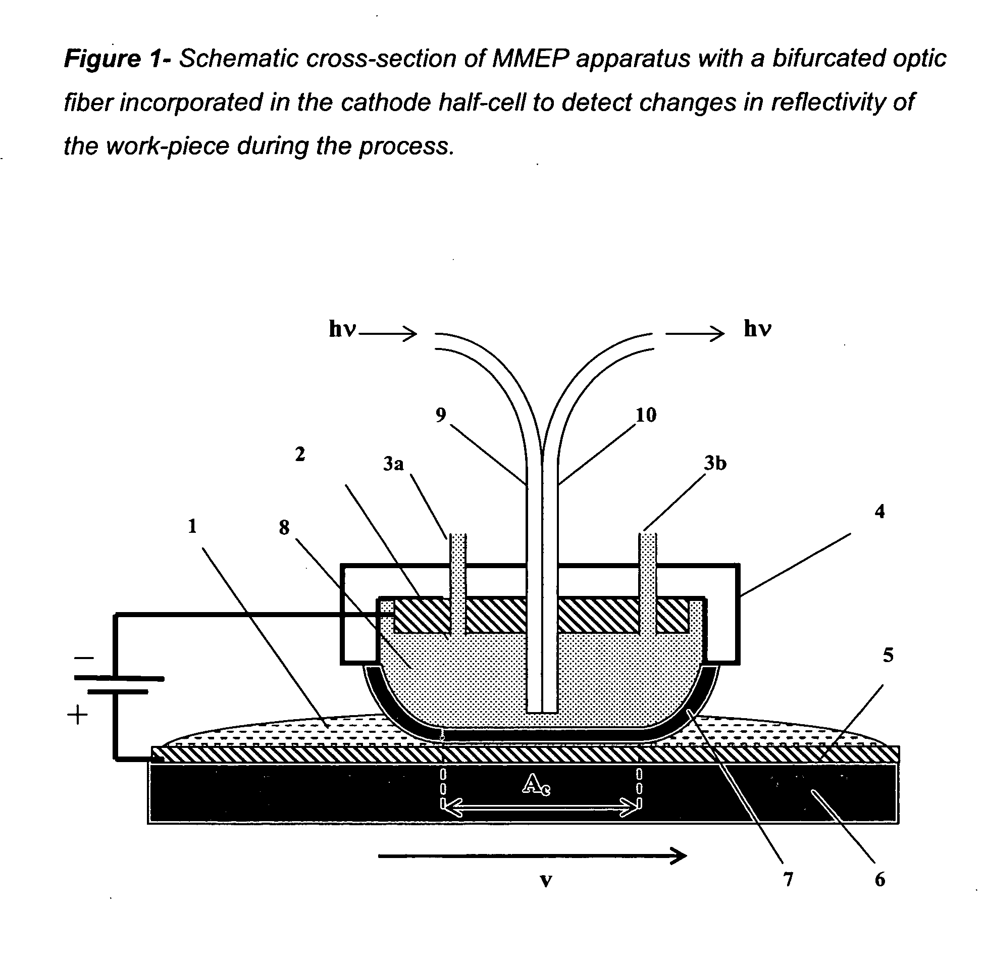
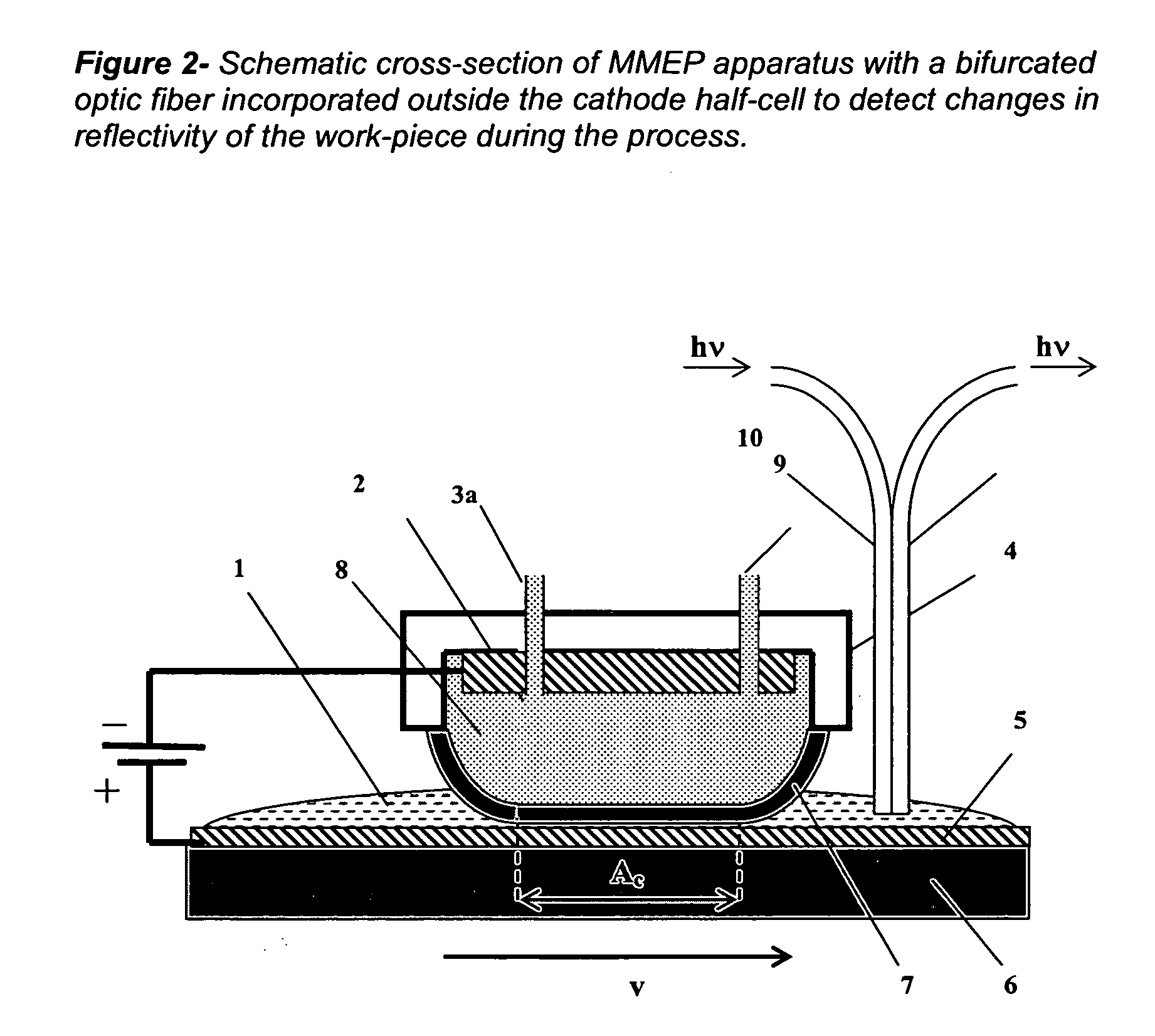
[0020]This invention is directed to optical methods and apparatuses for detecting in situ changes in the topography of a work-piece during the progress of MMEP. The optical apparatuses and methods can be used to detect in situ the point of breakthrough, where a thin metal coating is first cleared from certain areas of a substrate. The apparatuses and methods can also be used to detect in situ the end-point, where a thin metal coating has been entirely removed from raised, plateau areas on the substrate surface, prior to removal by MMEP of the metal coating from recessed areas of the substrate.

[0021]In an MMEP process, the workpiece is physically separated from the electrolyte and cathode by a charge-selective ion-conducting membrane, wherein the membrane is essentially impermeable to the electrolyte but permeable to the ions produced by anodic oxidation of the work piece. MMEP is described in co-pending applications (U.S. Ser. No. 10 / 976,897; U.S. Ser. No. 10 / 986,048; and U.S. Ser. ...


PUM

PropertyMeasurementUnit
Volumeaaaaaaaaaa
Transparencyaaaaaaaaaa

Abstract

Methods and apparatus for monitoring in situ the progress of planarization and / or removal of a thin metal layer from a substrate during membrane-mediated electropolishing processes are provided.

Description

FIELD OF THE INVENTION[0001]The invention is directed to methods and apparatuses for monitoring in situ the progress of planarization and / or removal of a thin metal layer from a substrate during membrane-mediated electropolishing processes.BACKGROUND[0002]Interconnections on integrated circuits are fabricated by the Cu damascene process in which the interconnect circuit pattern is lithographically etched into the surface of a dielectric layer on the surface of the wafer. The pattern is then coated with thin conformal layers of a barrier metal, such as Ta, followed by Cu. Additional Cu in then electroplated over the entire surface of a wafer to fill completely the recessed circuit features with Cu. It is then necessary to planarize topographic features on the surface of the electroplated Cu and remove all excess Cu from the plateau areas between the circuit features so that the underlying barrier metal is exposed. Planarization and removal of excess Cu is customarily achieved by a ch...

Claims


Application Information

Patent Timeline
IPC IPC(8): C25F3/16
CPCC25F7/00C25F3/16
Inventor MAZUR, STEPHEN
Owner EI DU PONT DE NEMOURS & CO
Learn More