Charged-particle detector

Inactive Publication Date: 2011-04-28
HAMAMATSU PHOTONICS KK
View PDF4 Cites 13 Cited by
  • Summary
  • Abstract
  • Description
  • Claims
  • Application Information

AI Technical Summary

Benefits of technology

[0016]Further, in the above-described charged-particle detector, it is preferable that the metal tube body has openings in its side wall, and the inside of the metal tube body and the outside thereof are communicated with each other via the openings. Because the charged-particle detector is disposed in vacuum (in a decompression environment less than one atmospheric pressure) to an extent that it is possible for ions to fly linearly such as in a chamber of a mass spectroscope, the inside of the chamber and the inside of the metal

Problems solved by technology

However, in a conventional ion detector, the output range within which the linearity of outputs can be retained is limited.
The reason for this is that, because an MCP is highly-resistive, and when a quantity of output electrons from the MCP is greater than a predetermined value, electrons to be output per unit time from the MCP are depleted,

Method used


Image

  • Charged-particle detector
  • Charged-particle detector
  • Charged-particle detector

Examples


Embodiment Construction

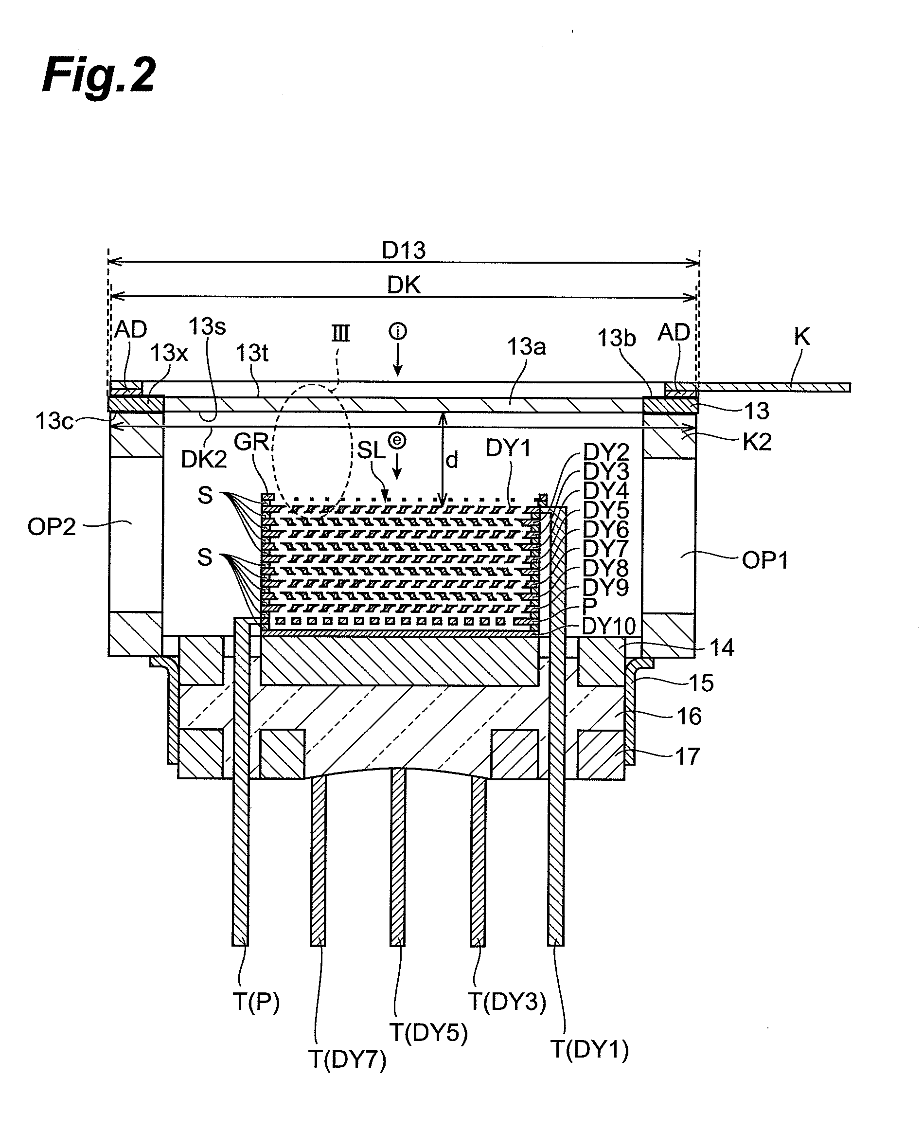
[0024]Hereinafter, a charged-particle detector according to an embodiment will be described by using an ion detector as an example. Note that the same components are denoted by the same reference numerals and letters, and overlapping descriptions will be omitted.

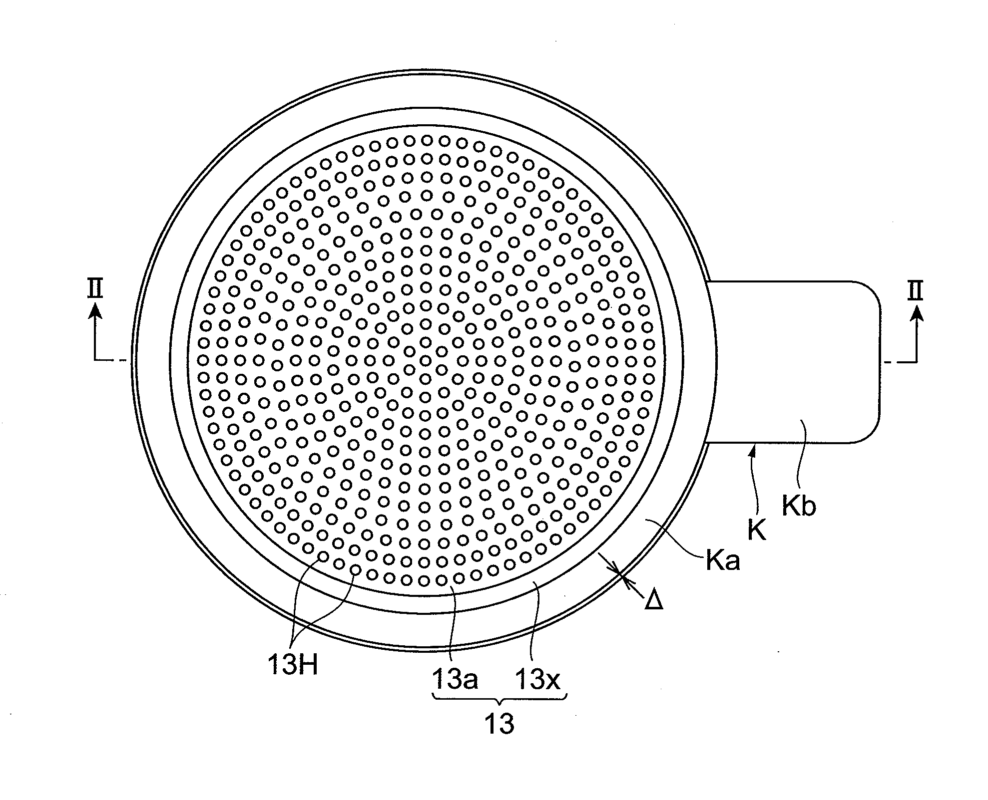
[0025]FIG. 1 is a plan view of an ion detector according to an embodiment.

[0026]The ion detector includes a micro-channel plate (MCP) 13. The main body of the MCP 13 is formed of an insulating body such as glass, and has a plurality of through holes 13H extending so as to be slightly inclined toward its thickness direction. A secondary electron emission material is formed on the inner walls of the through holes 13H functioning as an electron incoming plane (electron-multiplier plane). A region in which the through holes 13H are formed is an effective region 13a of the MCP 13, and a cathode electrode K is fixed to an annular peripheral region 13x located lateral to the effective region 13a. The cathode electrode K has an annu...


PUM


Abstract

This ion detector includes an MCP and a plurality of planar dynodes respectively having a plurality of slits. The plurality of planar dynodes are stacked via spacers parallel to an electron output plane of the MCP, and the first stage planar dynode is opposed parallel to the electron output plane. In accordance with this ion detector, it is possible to obtain output signals having the linearity reaching mV order, and to shorten its pulse width to approximately 600 ps.

Description

BACKGROUND OF THE INVENTION[0001]1. Field of the Invention[0002]The present invention relates to a charged-particle detector which is disposed in a vacuum chamber of a mass spectroscope or the like, to detect ions or electrons.[0003]2. Related Background Art[0004]A mass spectroscope performs mass spectrometry of ions by utilizing the fact that ions flying in a specific place differ in trajectory or velocity depending on their mass. That is, in the case in which ions are deflected by an electric field and / or a magnetic field, their deflection amounts are different depending on their mass, and therefore, the incoming positions of the ions to an ion detector are different depending on their mass. Further, in the case in which ions are accelerated in an electric field, the flying velocities of the accelerated ions are different depending on their mass, and therefore, the incoming timings of the ions to the ion detector are different depending on their mass.[0005]A mass spectroscope util...

Claims


Application Information

Patent Timeline
IPC IPC(8): H01J49/02
CPCH01J43/246H01J43/22
Inventor SUYAMA, MOTOHIROOHMURA, TAKAYUKIKOBAYASHI, HIROSHI
Owner HAMAMATSU PHOTONICS KK
Why Eureka
Try Eureka