Compressor

a compressor and compression mechanism technology, applied in the field of compressors, can solve the problems of deterioration in compressor performance and power loss, and achieve the effects of reducing the pressure of the oil passing through the decompression mechanism, and improving the decompression capacity of the decompression mechanism

Active Publication Date: 2020-05-26
HANON SYST
View PDF20 Cites 0 Cited by
  • Summary
  • Abstract
  • Description
  • Claims
  • Application Information

AI Technical Summary

Benefits of technology

[0027]A compressor according to the present invention includes an oil recovery passage that recovers oil to a suction space from an oil storage chamber in a discharge space and a decompression mechanism that reduces the pressure of the oil passing through the oil recovery passage. The decompression mechanism has an orifice hole, the inner diameter of which varies depending on the pressure in the oil storage chamber. Accordingly, it is possible to sufficiently decompress the oil recovered to the suction space from the discharge space even when the pressure in the discharge space is increased. Meanwhile, the pressure of the refrigerant discharged from a compression mechanism is irregular and may be higher than a predetermined pressure value. Thus, the pressure in the oil storage chamber may be higher than a predetermined pressure value. Therefore, the orifice hole of the decompression mechanism according to the present invention is configured such that the inner diameter of the orifice hole is reduced when the pressure in the oil storage chamber is increased. Accordingly, when the pressure in the oil storage chamber is increased, a decompression capacity of the decompression mechanism can be improved and the pressure of the oil passing through the decompression mechanism can be reduced compared to when the inner diameter of the orifice hole is fixed. That is, it is possible to reduce a flow rate of oil passing through the decompression mechanism and prevent introduction of oil, which is not sufficiently decompressed, into the suction space even though the pressure in the oil storage chamber is increased. Therefore, the pressure in the suction space can be maintained at a predetermined pressure value, with the consequence that it is possible to prevent a deterioration in compressor performance and a power loss.

Problems solved by technology

However, in the conventional compressor including the decompression mechanism 58, if the pressure in an oil storage chamber 54 is increased, the oil recovered from the oil storage chamber 54 to a suction space S1 is not sufficiently decompressed, which may lead to a deterioration in compressor performance and a power loss.
Hence, the pressure in the suction space S1 is higher than a predetermined pressure value, resulting in a deterioration in compressor performance and a power loss.

Method used


Image

  • Compressor
  • Compressor
  • Compressor

Examples


Embodiment Construction

[0036]A compressor according to exemplary embodiments of the present invention will be described below in detail with reference to the accompanying drawings.

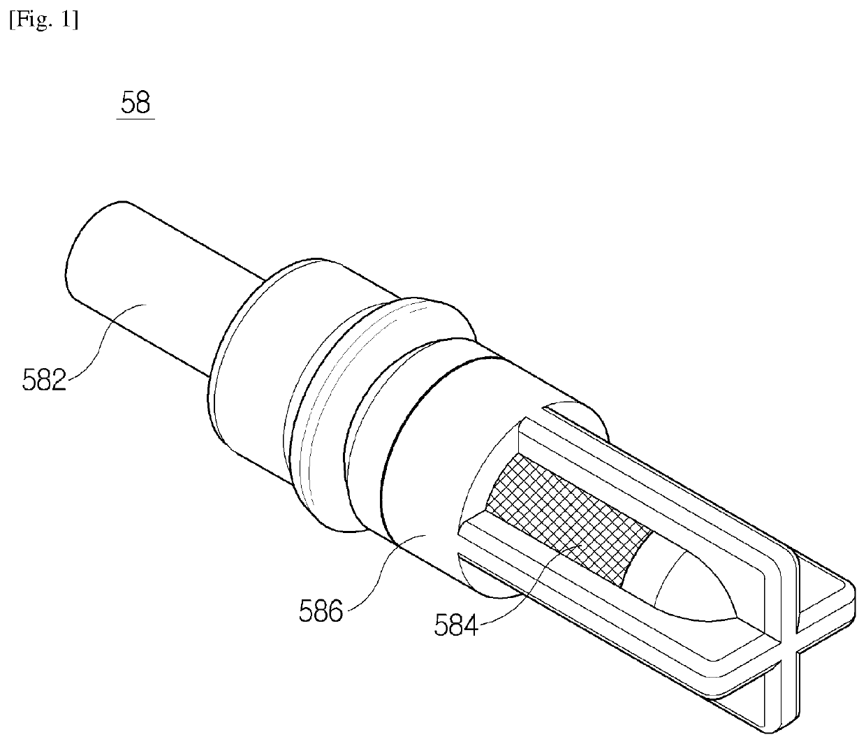
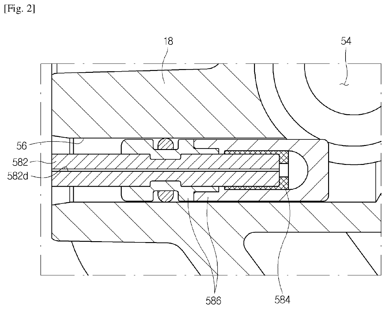
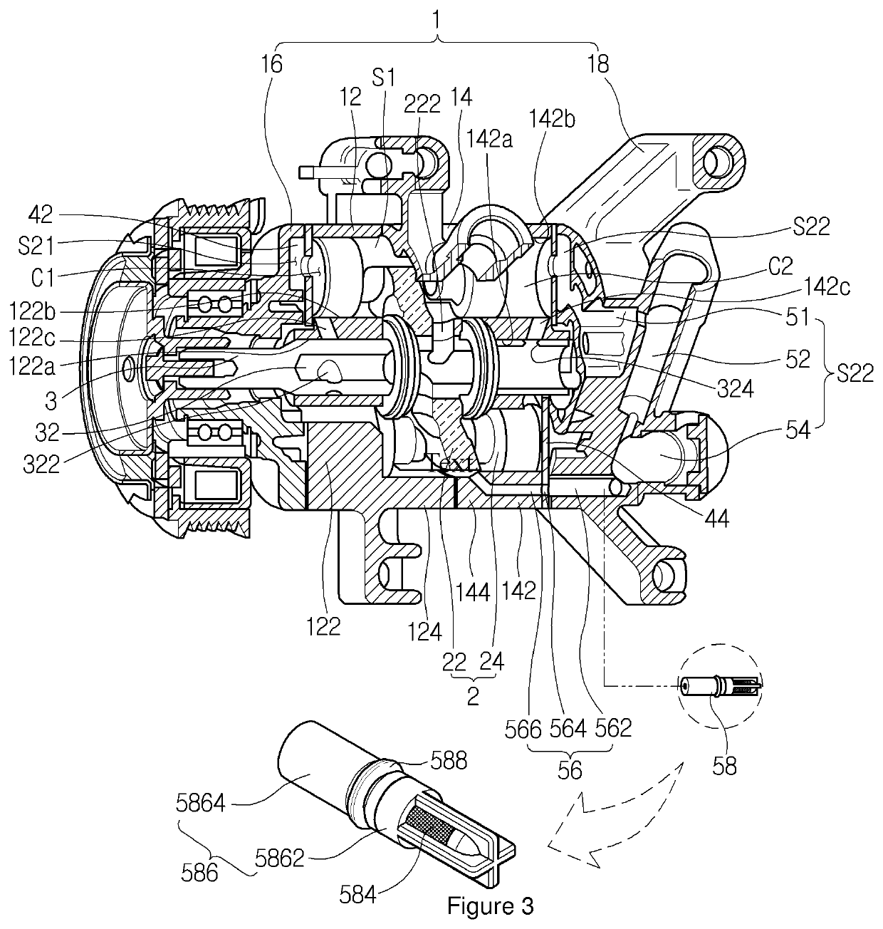
[0037]FIG. 3 is a perspective view illustrating a compressor according to an embodiment of the present invention. FIG. 4 is a cross-sectional view illustrating a state in which a decompression mechanism of FIG. 3 is mounted to the compressor. FIG. 5 is a cross-sectional view illustrating a state in which an orifice member of FIG. 4 is deformed by an increase in pressure in an oil storage chamber so that an inner diameter of an orifice hole is reduced.

[0038]Referring to FIGS. 3 to 5, the compressor according to the embodiment of the present invention may include a casing 1 having an internal space, a compression mechanism 2 that is provided in the casing 1 to compress a refrigerant, and a rotary shaft 3, one side of which is coupled to a drive source (for instance, a vehicle engine) (not shown) provided outside the casing 1 while...


PUM


Abstract

A compressor includes a compression mechanism configured to suck and compress a refrigerant from a suction space to discharge the refrigerant to a discharge space by a driving force transmitted thereto. The compressor includes an oil storage chamber provided in the discharge space to collect oil separated from the refrigerant discharged from the compression mechanism, an oil recovery passage configured to guide the oil in the oil storage chamber to the suction space, and a decompression mechanism provided in the oil recovery passage to reduce a pressure of the oil passing through the oil recovery passage by an orifice hole having an inner diameter smaller than the oil recovery passage. The decompression mechanism is configured such that, when a pressure in the oil storage chamber is increased, the inner diameter of the orifice hole is reduced.

Description

REFERENCE TO RELATED APPLICATIONS[0001]This application is a United States National Phase application of PCT / KR2017 / 002409 filed on Mar. 6, 2017, which claims priority to Korean Application No. 10-2016-0034804 filed on Mar. 23, 2016.TECHNICAL FIELD[0002]The present invention relates to a compressor, and more particularly, to a compressor capable of separating oil from a refrigerant, which is compressed and discharged, and decompressing and recovering the separated oil.BACKGROUND ART[0003]In general, a compressor serving to compress a refrigerant in a vehicle cooling system has been developed in various forms. The compressor includes a reciprocating compressor that compresses a refrigerant during reciprocation and a rotary compressor that compresses a refrigerant during rotation.[0004]The reciprocating compressor includes a crank compressor that transmits driving force from a drive source to a plurality of pistons using a crank, a swash plate compressor that transmits driving force f...

Claims


Application Information

Patent Timeline
Patent Type & Authority Patents(United States)
IPC IPC(8): F04B39/16F25B31/00F04C18/02F04C18/356F04C29/02F04C18/344F04C29/00F04B39/04F16K47/04F04B53/20F04B39/02
CPCF04C18/344F04B53/20F16K47/04F04B39/02F25B31/004F04C18/0207F04C18/356F04B39/16F04C29/0092F04B39/0284F04B39/04F04C29/028Y10T137/8085F04C2240/809Y10T137/7896F04C29/026F04B2205/50F16K15/142
Inventor HAM, SEOK JINKIM, MIN GYU
Owner HANON SYST
Why Eureka
Try Eureka