
Turbo machinery

Inactive Publication Date: 2011-04-28
HITACHI LTD
View PDF4 Cites 17 Cited by
  • Summary
  • Abstract
  • Description
  • Claims
  • Application Information

AI Technical Summary

Benefits of technology

[0017]On the other hand, generally, as for the diffuser, for a cost reduction of the compressor, better pressure recovery in a smaller diameter is strongly required. When the conventional diffuser without or with a guide vane is designated to be made smaller by decreasing the outlet diameter of the diffuser, since the channel width of the diffuser is fixed, the flow rate at the outlet of the diffuser is increased. The loss of an element (for example, the scroll, return channel, etc.) on the downstream side of the diffuser is proportional to the kinetic energy (dynamic pressure) at the outlet of the diffuser, so that a problem arises that the loss of the element on the downstream side is increased and the efficiency of the compressor is lowered.
[0018]An object of the present invention is to provide turbo machinery for preventing a back flow in the diffuser, improving the flow uniformity of the diffuser in the width direction, ensuring a wide operating range of the diffuser, maintaining the efficiency of the compressor, and reducing the casing diameter of the machinery.
[0021]According to the present invention, turbo machinery for preventing a back flow in the diffuser, improving the flow uniformity of the diffuser in the width direction, ensuring a wide operating range of the diffuser, maintaining the efficiency of the compressor, and reducing the casing diameter of the machinery can be realized.

Problems solved by technology

Hei 11 (1999)-82389, an appropriate angle for installing the guide vane on the channel wall surface to be enlarged is not disclosed, thus there are possibilities that only by installation of the guide vane, on the contrary, the performance of the diffuser may be deteriorated.
Further, only by installation of the guide vane, the guide vane cannot sufficiently fulfill a function as vanes for preventing the back flow on the channel wall surface and there are possibilities that the operating range of the diffuser may be narrowed.
The loss of an element (for example, the scroll, return channel, etc.) on the downstream side of the diffuser is proportional to the kinetic energy (dynamic pressure) at the outlet of the diffuser, so that a problem arises that the loss of the element on the downstream side is increased and the efficiency of the compressor is lowered.

Method used


Image

  • Turbo machinery
  • Turbo machinery
  • Turbo machinery

Examples


embodiment 1

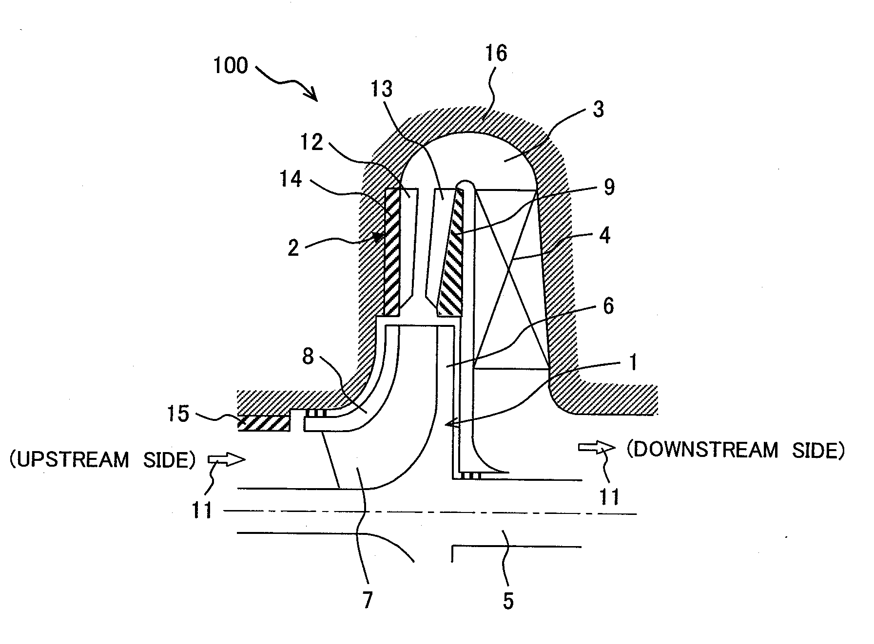
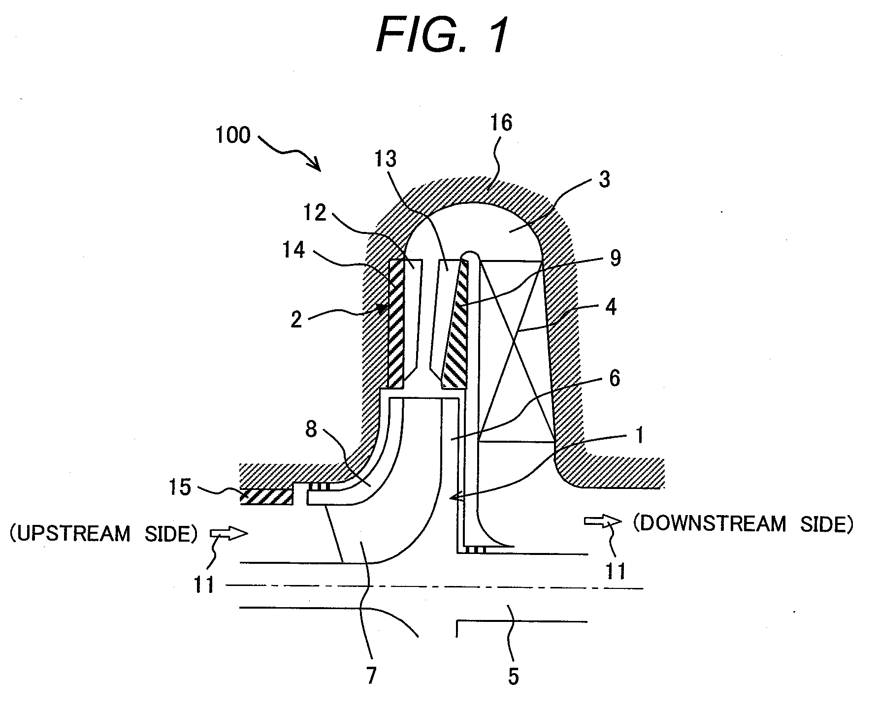
[0035]The centrifugal compressor which is turbo machinery of the first embodiment of the present invention will be explained in detail with reference to the accompanying drawings.

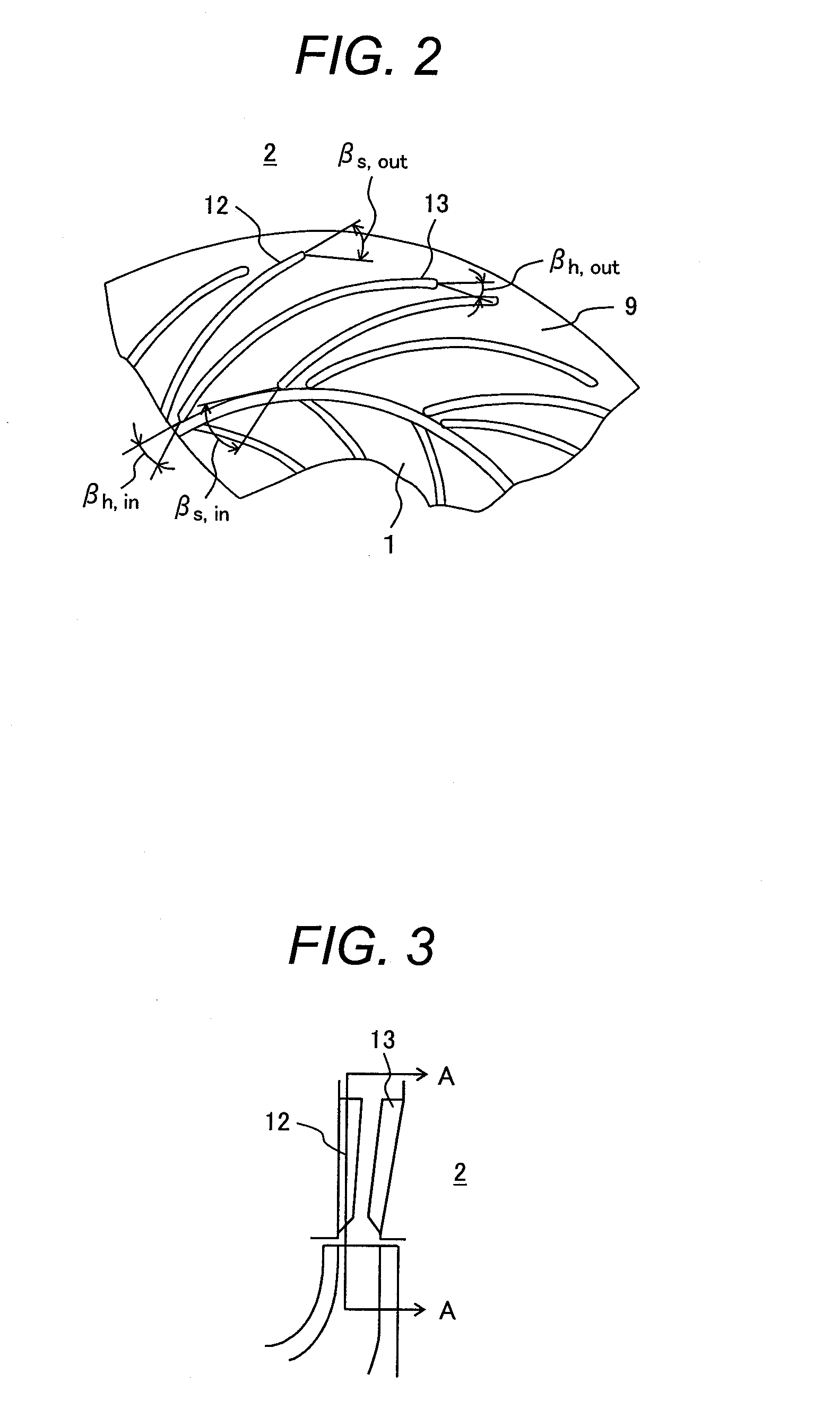
[0036]FIG. 1 is a cross sectional view showing the structure of a centrifugal compressor 100 relating to the first embodiment of the present invention and FIG. 2 shows the detailed vane of the diffuser of the centrifugal compressor 100 shown in FIG. 1.

[0037]As shown in FIG. 1, the centrifugal compressor 100 of this embodiment includes, in a casing 16, a rotary shaft 5 for driving rotation and an impeller 1 having a plurality of vanes 7 which are installed on the outer side of the rotary shaft 5, guide the flow of a working fluid 11 between a shroud 8 and a hub 6, and are arranged away from each other.

[0038]Inside the casing 16 and outside in the radial direction of the impeller 1 on the downstream side of the impeller 1, a diffuser 2 having vanes 12 and 13 is installed.

[0039]Inside the casing 16 on the down...

embodiment 2

[0084]Next, the diffuser 2 of the centrifugal compressor 100 of the second embodiment of the present invention will be explained.

[0085]The diffuser 2 of the centrifugal compressor 100 of this embodiment is similar to the diffuser 2 of the centrifugal compressor 100 of the first embodiment explained previously in the basic constitution, so that the explanation of the common portions of the constitution of the two is omitted and only the different portions will be explained below.

[0086]FIGS. 8 to 11 showing each of the diffusers 2 of the centrifugal compressor 100 show the channel form of the diffuser 2 installed on the downstream side of the impeller 1 of the centrifugal compressor 100 and the flow (the speed on the meridian plane) distribution of the working fluid flowing inside the diffuser 2, showing a constitution that the channel width of the diffuser 2 is enlarged from the upstream side to the downstream side.

[0087]Among them, FIGS. 10 and 11 showing the diffuser 2 of this embo...


PUM


Abstract

Turbo machinery comprising an impeller and a diffuser positioned on a downstream side of the impeller that a channel wall surface of the diffuser is composed of a pair of a shroud side diffuser plate and a hub side diffuser plate which surface each other and a channel width is formed so as to be increased downstream, characterized in that guide vanes in a circular arc shape lower in height than the channel width are installed in a line of a plurality of vanes on both channel walls of the shroud side diffuser plate and hub side diffuser plate of the diffuser, and a total of vane heights of the two guide vanes at an outlet of the diffuser is set so as to be within a range from 30 to 70% of the channel width at the outlet of the diffuser.

Description

CLAIM OF PRIORITY[0001]The present application claims priority from Japanese patent application JP 2009-243228 filed on Oct. 22, 2009, the content of which is hereby incorporated by reference into this application.BACKGROUND OF THE INVENTION[0002]1. Field of the Invention[0003]The present invention relates to turbo machinery and more particularly to turbo machinery such as a centrifugal compressor or a centrifugal fan that maintains high performance and is suitable for a compressor with a small sized casing.[0004]2. Description of Related Art[0005]A centrifugal compressor which is one of the turbo machineries for compressing a fluid by a rotating impeller is conventionally used widely in various plants. Recently, due to energy problems and environmental problems, the life cycle cost including the running cost thereof is apt to be regarded as important and a compressor for realizing high efficiency in a wide operating range is required.[0006]In consideration of an operation in a fixe...

Claims


Application Information

Patent Timeline
IPC IPC(8): F04D29/44
CPCF04D17/12F04D29/681F04D29/444F05D2250/52
Inventor SHIBATA, TAKANORIYAGI, MANABUNISHIDA, HIDEOKOBAYASHI, HIROMITANAKA, MASANORI
Owner HITACHI LTD
Learn More