System and method for use of nanoparticles in imaging and diagnosis

a nanoparticle and imaging technology, applied in the field of noninvasive imaging of magnetic particles, can solve problems such as impracticality in arrangement, and achieve the effects of improving sensitivity, speeding up or improving the signal-to-noise ratio of imaging, and improving the sensitivity of magnetic particle imaging (mpi)

Active Publication Date: 2011-04-28
TRUSTEES OF DARTMOUTH COLLEGE THE
View PDF25 Cites 29 Cited by
  • Summary
  • Abstract
  • Description
  • Claims
  • Application Information

AI Technical Summary

Benefits of technology

[0022]This invention overcomes the disadvantages of the prior art by providing a system and method that improves the sensitivity and localization capabilities of Magnetic Particle Imaging (MPI) by using combinations of static and oscillating magnetic fields. Combinations of magnetic fields can be used to distribute the signals coming from the magnetic particles among the harmonics in specific ways to improve sensitivity and to provide localization information to speed up or improve the signal-to-noise ratio (SNR) of imaging and / or eliminate the need for saturation fields currently used in MPI. In one embodiment, the signal from particles along a static or slowly varying magnetic field are collected rather than collecting signal only from the field free point, in contrast to the prior art, improving the signal and allowing smaller gradients or better signal-to-noise ratio (SNR) to be achieved. In another embodiment, the second harmonic signal from nanoparticles can be enabled by a localized static field scanned across the object rather than saturating the third harmonic to achieve localization as in prior art. In another embodiment, the static field of an MRI system can be used to create a field offset allowing the signal in the second harmonic to be detected, rather than using only the signal at the third harmonic, to create a combined imaging modality where the particles are imaged using magnetic particle imaging and the anatomy is imaged using conventional magnetic resonance imagery (MRI). In another embodiment, a combination of harmonic fields can be used to place the harmonics at frequencies that are not harmonics of the amplifiers so as to reduce noise and provide extra localization information.

Problems solved by technology

This arrangement may be impractical, as it impeded access to the examination area.

Method used


Image

  • System and method for use of nanoparticles in imaging and diagnosis
  • System and method for use of nanoparticles in imaging and diagnosis
  • System and method for use of nanoparticles in imaging and diagnosis

Examples


Embodiment Construction

I. Improved Localization and Imaging

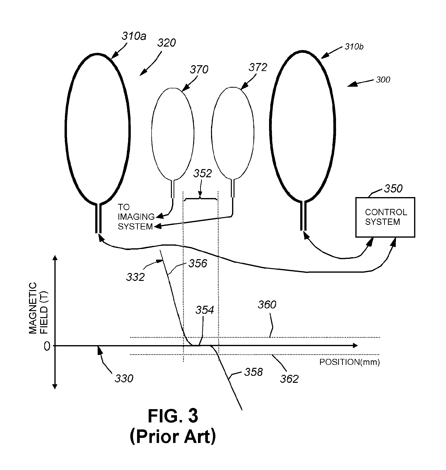
[0053]Reference is made to FIG. 3 which again describes a simplified MPI system 300 like the MPI system described above with reference to FIG. 1. This system 300 is again discussed and illustrated for the purposes of comparison with the following improved system arrangements described below. The views and graphs depicted are generally two-dimensional, but should be taken to describe the resulting field characteristics in three dimensions. The system 300 consists of groups of drive and selection coils 310a and 310b that define therebetween a magnetic field region 320 that can be characterized by the graph 330. The curve 332 defines the magnetic field across the subject produced by the coils to localize the nanoparticle signal versus position within to the region 320 (e.g. distance from either coil 310a, 310b). As described above, the selection and drive coils are operatively connected with a control system 350. The control system includes appropria...


PUM


Abstract

A method for diagnosing certain types of cancers provides a nanoparticle agent to be uptaken by cancer cells for diagnosis and treatment of certain cancers. A compound containing nanoparticles is directed toward a tumor site, and then a predetermined time period passes to allow the nanoparticles to be uptaken by the cancer cells. Imaging is then performed on the nanoparticles by an appropriate imaging device to determine the concentration of nanoparticles uptaken by the cancer cells. Finally, image data provided by the imaging device is analyzed to determine the concentration of nanoparticles and thereby determine whether a tumor is present. The nanoparticle agent can further be employed as a treatment of certain cancers. After the uptake of nanoparticles into the cells, a predetermined field applied to the nanoparticles for a sufficient period of time activates the magnetic cores of the nanoparticles to include hyperthermia-mediated destruction of the cancer cells.

Description

RELATED APPLICATIONS[0001]This application is a continuation-in-part of copending U.S. application Ser. No. 12 / 141,844, filed Jun. 18, 2008, entitled SYSTEM AND METHOD FOR USE OF NANOPARTICLES IN IMAGING AND TEMPERATURE MEASUREMENT, the entire disclosure of which is herein incorporated by reference, which claims the benefit of U.S. Provisional Application Ser. No. 60 / 944,901, filed Jun. 19, 2007, entitled SYSTEM AND METHOD FOR IMPROVED NANOPARTICLE LOCALIZATION AND IMAGING, the entire disclosure of which is herein incorporated by reference, and U.S. Provisional Application Ser. No. 60 / 974,105, filed Sep. 21, 2007, entitled SYSTEM AND METHOD FOR MEASURING TEMPERATURE USING THE SPECTRAL DISTRIBUTION OF MAGNETIC PARTICLE IMAGING SIGNALS, the entire disclosure of which is herein incorporated by reference.STATEMENT REGARDING FEDERALLY SPONSORED RESEARCH OR DEVELOPMENT[0002]This invention was made with U.S. government support under Grant Numbers R01CA124515, R21CA132026 and F31CA134188, a...

Claims


Application Information

Patent Timeline
Patent Type & Authority Applications(United States)
IPC IPC(8): A61B5/055
CPCA61B5/05A61B5/0515A61B5/055H01F1/0045G01R33/4808G01R33/5601B82Y25/00
Inventor WEAVER, JOHN B.CONEJO-GARCIA, JOSE R.FIERING, STEVEN N.RAUWERDINK, ADAM M.SCARLETT, UCIANE K.
Owner TRUSTEES OF DARTMOUTH COLLEGE THE
Why Eureka
Try Eureka