Membrane cleaning with pulsed arilift pump

a technology of arilift pump and membrane, which is applied in the direction of membranes, filtration separation, separation processes, etc., can solve the problems of inability to maintain a constant flow of filtrate, inability to clean membranes, so as to reduce the residence time, improve the quality of filtrate, and improve the effect of filter quality

Active Publication Date: 2011-05-05
EVOQUA WATER TECH LLC
View PDF100 Cites 63 Cited by
  • Summary
  • Abstract
  • Description
  • Claims
  • Application Information

AI Technical Summary

Benefits of technology

[0011]Optionally, an additional source of bubbles may be provided in said liquid medium by means of a blower or like device. The gas used may include air, oxygen, gaseous chlorine, ozone, nitrogen, methane or any other gas suitable for a particular application. Air is the most economical for the purposes of scrubbing and / or aeration. Gaseous chlorine may be used for scrubbing, disinfection and enhancing the cleaning efficiency by chemical reaction at the membrane surface. The use of ozone, besides the similar effects mentioned for gaseous chlorine, has additional features, such as oxidizing DBP precursors and converting non-biodegradable NOM's to biodegradable dissolved organic carbon. In some applications, for example, an anaerobic biological environment or a non-biological environment where oxygen or oxidants are undesirable, nitrogen may be used, particularly where the feed tank is dosed with ability to capture and recycle the nitrogen.
[0013]Where a set of membrane modules are used, the modules are generally assembled in an array, rack or a cassette located in a feed containing vessel or tank. To clean a rack or a cassette of membrane modules, the device for providing the pulsed gas or two-phase gas / liquid flow can be connected to a distributor and the pulsed gas bubbles generated are distributed into the modules through the distributor. It is preferred to arrange one device to one module or to a small number of modules. Accordingly, there typically are a number of devices installed for one rack or cassette. Gas is preferably supplied to the rack and then distributed to each device along the rack manifold. Although the gas is supplied to individual device in a continuous mode, the eruption of gas bubbles from the devices along the rack is produced at random times, keeping the membrane tank feed essentially constantly in an unstable condition. This effect reduces solid concentration polarisation and hence the filtration resistance. When looking down from the top of a rack, gas bubbles appear randomly from different modules within the rack, forming a random distribution pattern.
[0017]According to one preferred form, the present invention provides a method of removing fouling materials from the surface of a plurality of porous hollow fiber membranes mounted and extending longitudinally in an array to form a membrane module, said membranes being arranged in close proximity to one another and mounted to prevent excessive movement therebetween, the method comprising the steps of providing a generally random, uniformly distributed pulsed gas bubble flow past the surfaces of said membranes, said distribution being such that said bubbles flow substantially uniformly between each membrane in said array to scour the surface of said membranes and remove accumulated solids from within the membrane module.
[0024]Preferably, the fibers may be protected and fiber movement is limited by a module support screen which has both vertical and horizontal elements appropriately spaced to provide unrestricted fluid and gas flow through the fibers and to restrict the amplitude of fiber motion reducing energy concentration at the potted ends of the fibers.
[0035]If required, a further source of aeration may be provided within the tank to assist microorganism activity. For preference, the membrane module is suspended vertically within the tank and said further source of aeration may be provided beneath the suspended module. Preferably, the further source of aeration comprises a group of air permeable tubes. The membrane module may be operated with or without backwash depending on the flux and feed condition. A high mixed liquor of suspended solids (5,000 to 20,000 ppm) in the bioreactor has been shown to significantly reduce residence time and improve filtrate quality. The combined use of aeration for both degradation of organic substances and membrane cleaning has been shown to enable constant filtrate flow without significant increases in transmembrane pressure while establishing high concentration of MLSS.

Problems solved by technology

However, the capital and operating cost can be prohibitive.
However, this method consumes large amounts of energy.
Moreover, in an environment of high concentration of solids, the gas distribution system may gradually become blocked by dehydrated solids or simply be blocked when the gas flow accidentally ceases.
In order to provide for such cyclic operation, such systems normally require complex valve arrangements and control devices which tend to increase initial system cost and ongoing maintenance costs of the complex valve and switching arrangements required.
Cyclic frequency is also limited by mechanical valve functioning in large systems.
Moreover, cyclic aeration has been found to not effectively refresh the membrane surface.

Method used


Image

  • Membrane cleaning with pulsed arilift pump
  • Membrane cleaning with pulsed arilift pump
  • Membrane cleaning with pulsed arilift pump

Examples


examples

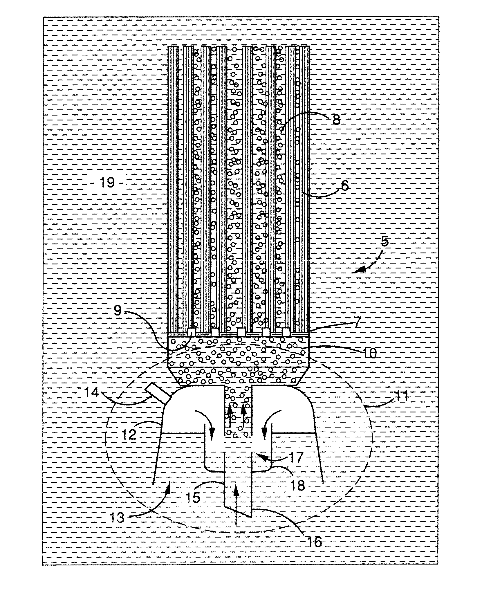
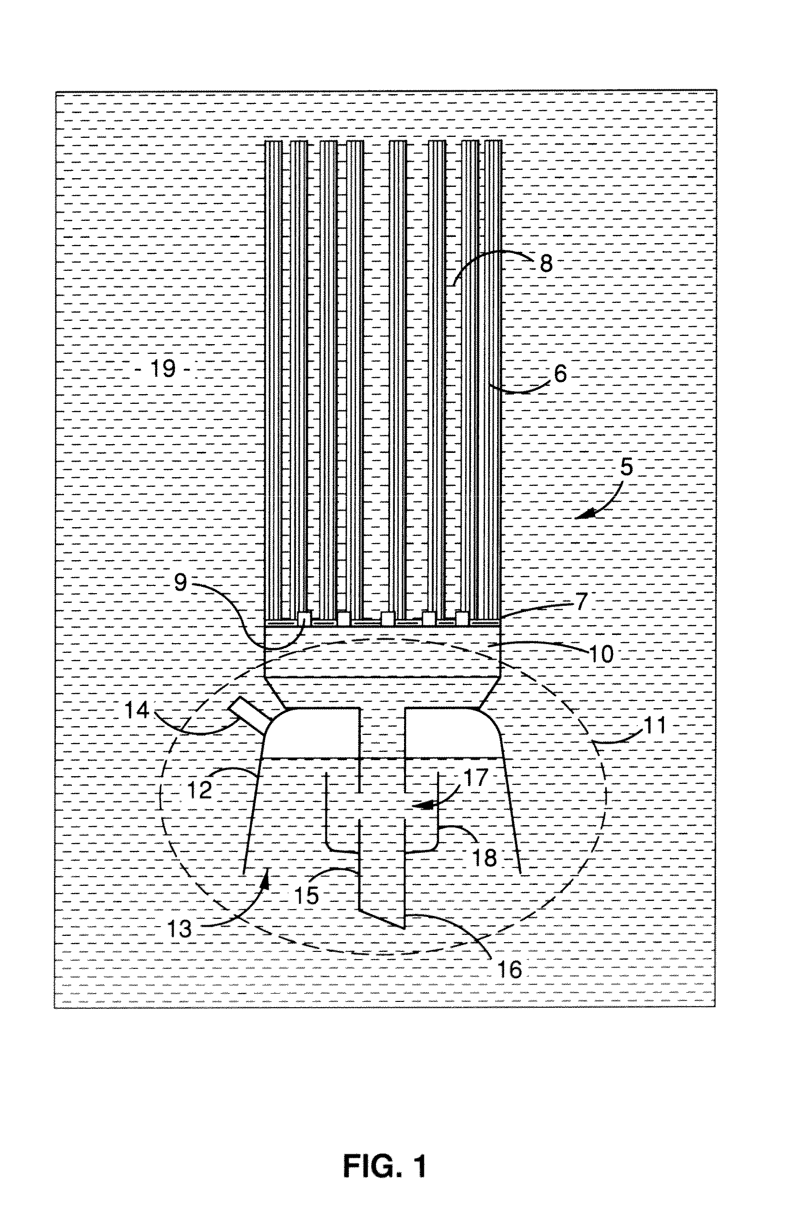
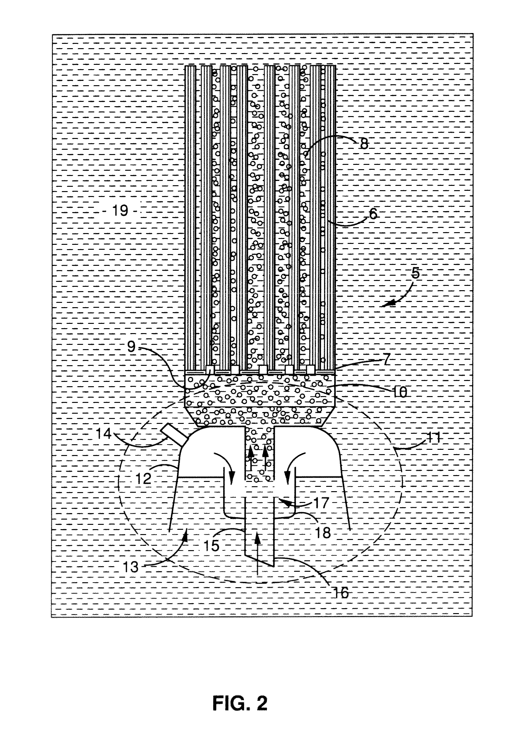
[0074]One typical membrane module is composed of hollow fiber membranes, has a total length of 1.6 m and a membrane surface area of 38 m2. A pulsed flow generating device was connected to the typical membrane module. A paddle wheel flowmeter was located at the lower end of the riser tube to monitor the pulsed liquid flow-rate lifted by gas. FIG. 10 shows a snapshot of the pulsed liquid flow-rate at a constant supply of gas flow at 7.8 Nm3 / hr. The snapshot shows that the liquid flow entering the module had a random or chaotic pattern between highs and lows. The frequency from low to high liquid flow-rates was in the range of about 1 to 4.5 seconds. The actual gas flow-rate released to the module was not measured because it was mixed with liquid, but the flow pattern was expected to be similar to the liquid flow—ranging between highs and lows in a chaotic nature.

[0075]A comparison of membrane cleaning effect via pulsed and normal airlift devices was conducted in a membrane bioreactor....


PUM

PropertyMeasurementUnit
diameteraaaaaaaaaa
diameteraaaaaaaaaa
inner diameteraaaaaaaaaa

Abstract

A method of cleaning a membrane surface immersed in a liquid medium with a fluid flow, including the steps of providing a randomly generated intermittent or pulsed fluid flow along the membrane surface to dislodge fouling materials therefrom. A membrane module is also disclosed comprising a plurality of porous membranes (6) or set of membrane modules (5) and a device (11) for providing a generally randomly generated, pulsed fluid flow such that, in use, said fluid flow moves past the surfaces of said membranes (6) to dislodge fouling materials therefrom.

Description

CROSS REFERENCE TO RELATED APPLICATIONS[0001]This application is a continuation application of U.S. application Ser. No. 12 / 602,316 filed on May 29, 2008, entitled MEMBRANE CLEANING WITH PULSED AIRLIFT PUMP, which is a U.S. national stage application and claims the benefit under 35 U.S.C. §371 of International Application No. PCT / US2008 / 006799 filed on May 29, 2008, entitled MEMBRANE CLEANING WITH PULSED AIRLIFT PUMP, which claims priority under 35 U.S.C. §119(e) to U.S. Provisional Application Ser. No. 60 / 940,507, entitled MEMBRANE CLEANING WITH PULSED AIRLIFT PUMP, filed on May 29, 2007, each of which is herein incorporated by reference in their entirety for all purposes and to which this application claims the benefit of priority.TECHNICAL FIELD[0002]The present invention relates to membrane filtration systems and, more particularly, to apparatus and related methods to effectively clean the membranes used in such systems by means of pulsed fluid flow.BACKGROUND OF THE INVENTION[0...

Claims


Application Information

Patent Timeline
Patent Type & Authority Applications(United States)
IPC IPC(8): B01D61/20B01D65/08C02F3/00B01D65/02C02F1/44C02F3/06C02F3/12B01D61/18B01D63/04
CPCB01D63/024B01D63/04B01D65/02B01D65/08B01D65/10C02F1/001B01D2313/26B01D2315/06B01D2321/185B01D2321/2066C02F3/1273B01D2313/21Y02W10/10B01D61/18B01D61/20B01D63/00C02F1/44C02F2303/16B01D63/02
Inventor ZHA, FUFANGJAMES, GERINZUBACK, EDWARD JOSEPHZAUNER, PETERPHELPS, ROGER WILLIAM
Owner EVOQUA WATER TECH LLC
Why Eureka
Try Eureka