
Variable geometry electric machine

a technology of electric machines and geometry, applied in the direction of dynamo-electric machines, electrical apparatus, magnetic circuit shapes/forms/construction, etc., can solve the problems of loss of conductivity available to drive the current in the motor, and the loss of copper in the stator coil, so as to achieve the effect of further increasing the speed of the machin

Inactive Publication Date: 2011-05-05
GM GLOBAL TECH OPERATIONS LLC
View PDF12 Cites 7 Cited by
  • Summary
  • Abstract
  • Description
  • Claims
  • Application Information

AI Technical Summary

Benefits of technology

[0006]In accordance with the teachings of the present invention, a variable geometry electric machine is disclosed that includes a moveable magnetic member that varies the geometry of the flux path between a rotor and a stator of the machine depending on the machine speed to control the flux linkage between the rotor and the stator. As the speed of the machine increases, the magnetic member is selectively withdrawn in an axial direction from between the rotor and the stator so that at higher machine speeds, the back EMF of the machine is reduced so that the speed of the machine can be further increased. The magnetic member includes a plurality of spaced apart magnetic strips mounted to a non-magnetic hub. In one embodiment, the magnetic strips are positioned within an air gap between the rotor and the stator and against ends of teeth of the stator, where stator coils are positioned between the teeth. In another embodiment, the magnetic strips are positioned within the teeth of the stator.

Problems solved by technology

However, because the induced voltage is proportional, especially as the speed of the machine increases, the back electro-motive force (EMF) generated by the machine also increases as the machine speed increases until it reaches the DC bus voltage, generally battery voltage, which results in a loss of conductivity available to drive the current in the motor that acts to limit the speed of the machine.
However, injecting current into the machine magnet causes a high copper loss in the stator coils, and therefore high losses in the machine.
Thus, flux weakening reduces the machine efficiency and power factor and increases the machine inverter current requirements.

Method used


Image

  • Variable geometry electric machine
  • Variable geometry electric machine
  • Variable geometry electric machine

Examples


Embodiment Construction

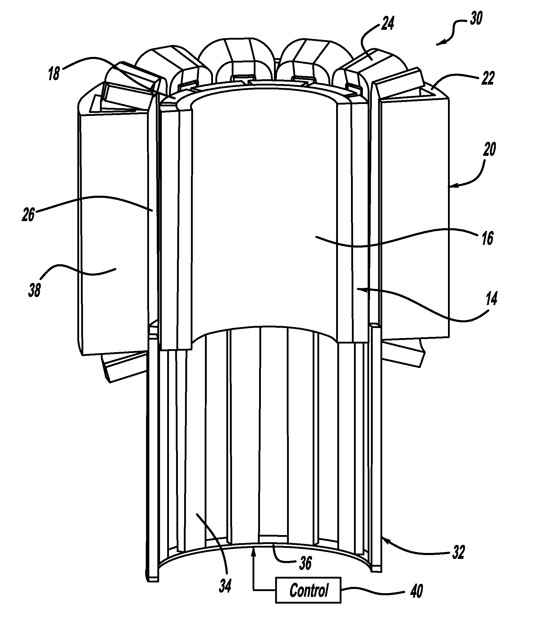
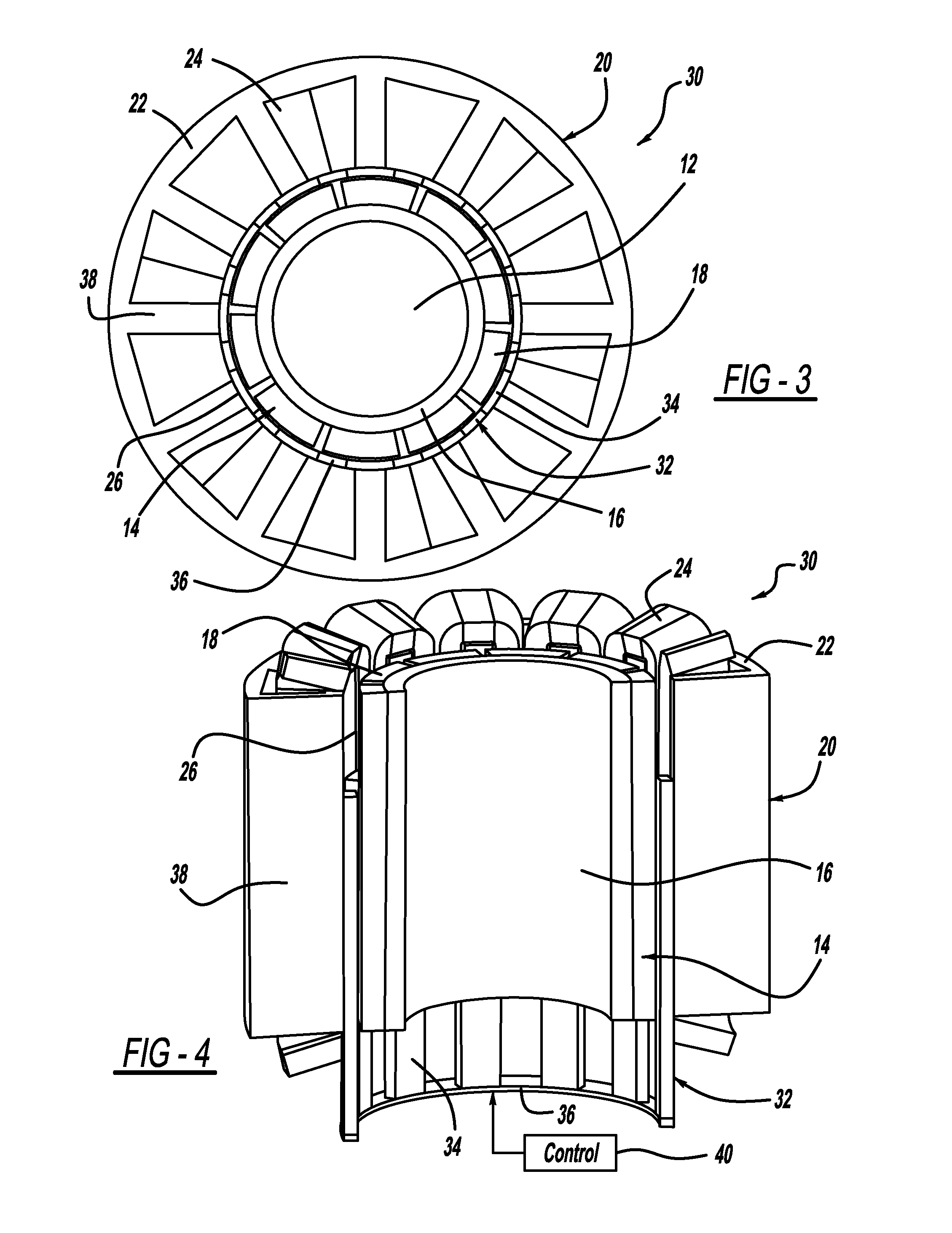
[0021]The following discussion of the embodiments of the invention directed to a variable geometry electric machine that includes a moveable magnetic member that links the main flux of the machine and is movable to reduce the flux as the speed of the machine increases to reduce the back EMF is merely exemplary in nature, and is in no way intended to limit the invention or its applications or uses.

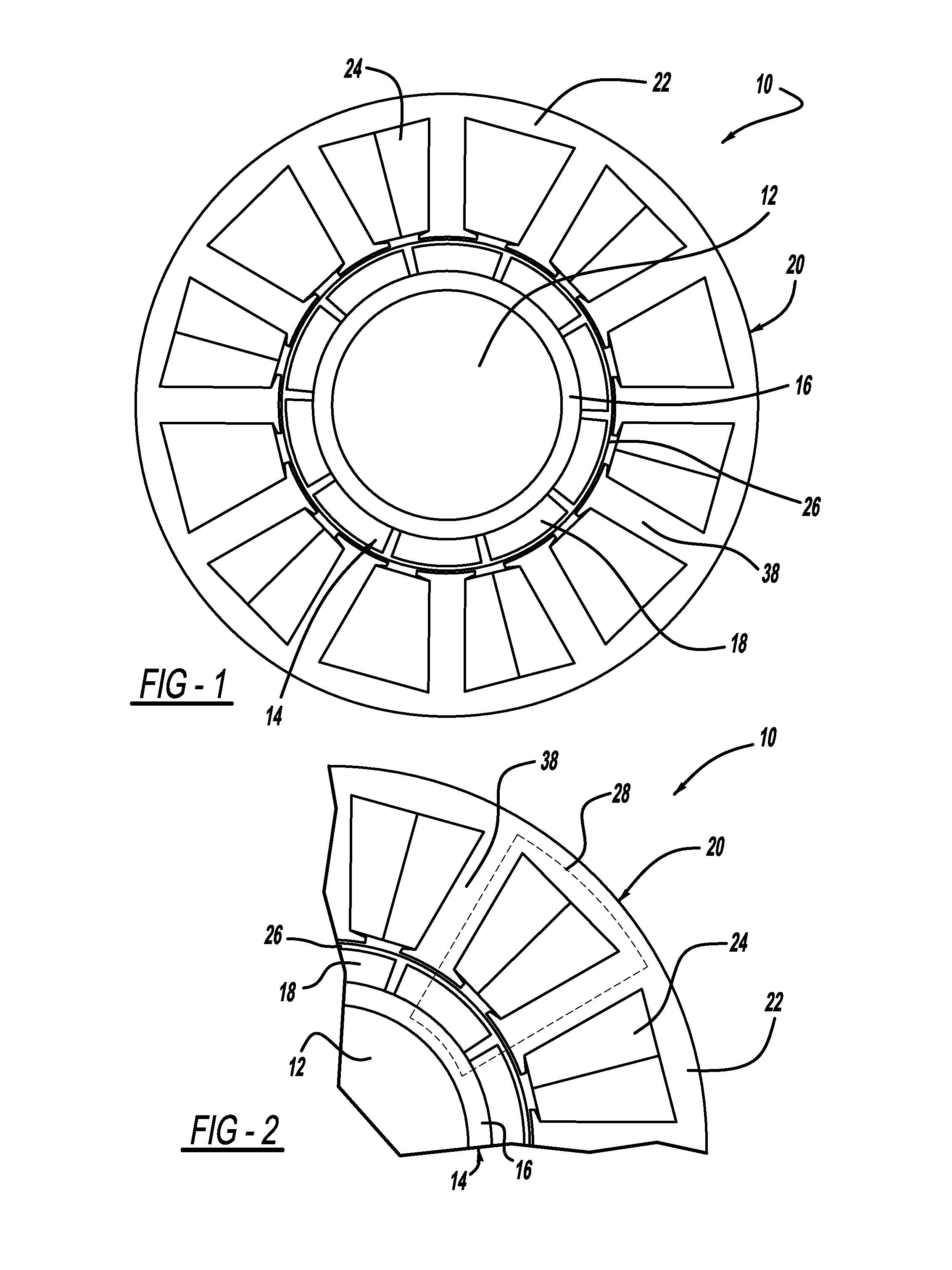
[0022]FIG. 1 is a cross-sectional view and FIG. 2 is a quarter section view of a conventional permanent magnet (PM) electric machine 10. The electric machine 10 includes a center shaft 12 surrounded by and mounted to a cylindrical rotor 14. The rotor 14 includes a rotor core 16 on which is mounted a plurality of permanent magnets 18, specifically ten magnets in this non-limiting example. The machine 10 also includes a cylindrical stator 20 including a stator core 22 having spaced apart teeth 38 and a plurality of stator coils 24 positioned between the teeth 38. In this non-limiting example ...


PUM


Abstract

A variable geometry electric machine that includes a moveable magnetic member that varies the flux path between a rotor and a stator of the machine depending on the machine speed to control the flux between the rotor and the stator. As the speed of the machine increases, the magnetic member is selectively withdrawn in an axial direction from between the rotor and the stator so that at higher machine speeds, the back EMF of the machine is reduced so that the speed of the machine can be increased. The magnetic member includes spaced apart magnetic strips mounted to a non-magnetic hub. In one embodiment, the magnetic strips are positioned within an air gap between the rotor and the stator and against ends of teeth of the stator, where stator coils are positioned between the teeth. In another embodiment, the magnetic strips are positioned within the teeth of the stator.

Description

BACKGROUND OF THE INVENTION[0001]1. Field of the Invention[0002]This invention relates generally to a variable geometry electric machine and, more particularly, to a permanent magnet electric machine that employs a magnetic member positioned within an air gap between a rotor and a stator of the machine, where the magnetic member is movable in an axial direction to change the flux link between the rotor and the stator to provide high torque at low speeds and reduce the back EMF at high speeds of the machine.[0003]2. Discussion of the Related Art[0004]An electric machine having a wide speed range is essential for automotive propulsion systems, such as for hybrid vehicles, electric vehicles, fuel cell vehicles, etc., and for power generation applications. In order to maximize the torque / ampere ratio, the electric machine is typically designed to have as high of an induced voltage-to-speed ratio as possible. However, because the induced voltage is proportional, especially as the speed o...

Claims


Application Information

Patent Timeline
Patent Type & Authority Applications(United States)
IPC IPC(8): H02K1/12
CPCH02K21/028
Inventor HAO, LEINAMUDURI, CHANDRA S.
Owner GM GLOBAL TECH OPERATIONS LLC
Features
  • Generate Ideas
  • Intellectual Property
  • Life Sciences
  • Materials
  • Tech Scout
  • Unparalleled Data Quality
  • Higher Quality Content
  • 60% Fewer Hallucinations
Learn More