

Synchronous electric motor system
a technology of synchronous electric motors and synchronous motors, applied in the direction of electronic commutation motor control, motor/generator/converter stoppers, dynamo-electric converter control, etc., can solve the problems of increasing switching loss and reducing switching loss
- Summary
- Abstract
- Description
- Claims
- Application Information
AI Technical Summary
Benefits of technology
Problems solved by technology
Method used
Image


Examples
embodiment 1
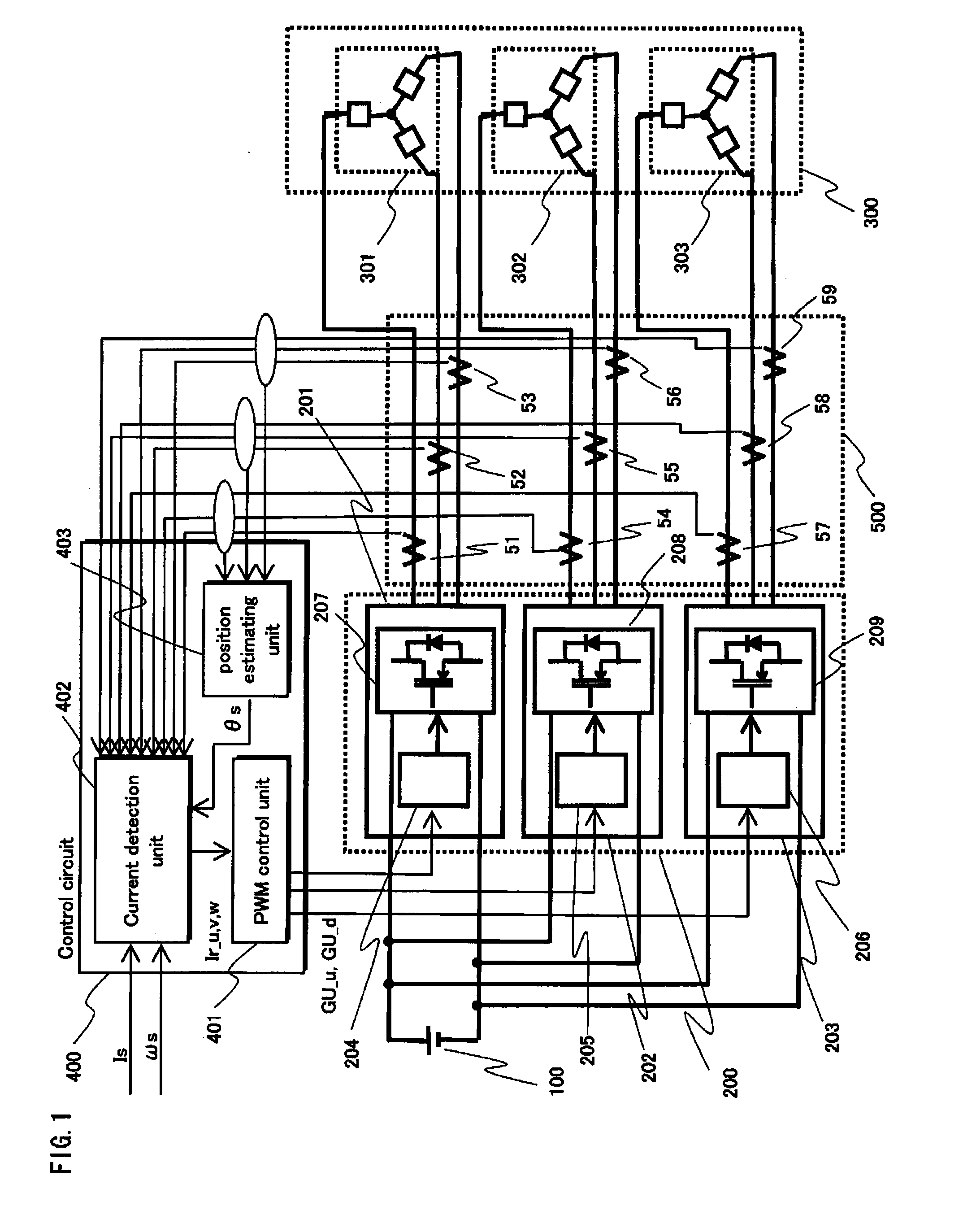
[0047]FIG. 1 shows an overall structure of a synchronous motor drive system pertaining to Embodiment 1 of the present invention.
[0048]The synchronous motor drive system includes a DC power source 100, an inverter group 200, a synchronous motor 300, a control circuit 400 and a current detection module 500.
[0049]The DC power source 100 provides direct current to the inverter group 200.
[0050]The inverter group 200 includes three-phase inverters 201, 202 and 203. Each of the three-phase inverters 201, 202 and 203 performs DC-AC conversion according to a gate control signal from the control circuit 400, and provides three-phase alternate current to the synchronous motor 300. The three-phase inverter 201, 202 and 203 are composed of power circuits 207, 208 and 209 and gate drive circuits 204, 205 and 206 corresponding to the power circuits, respectively. All the switching devices included in the three-phase inverters 201, 202 and 203 are included in a single module.
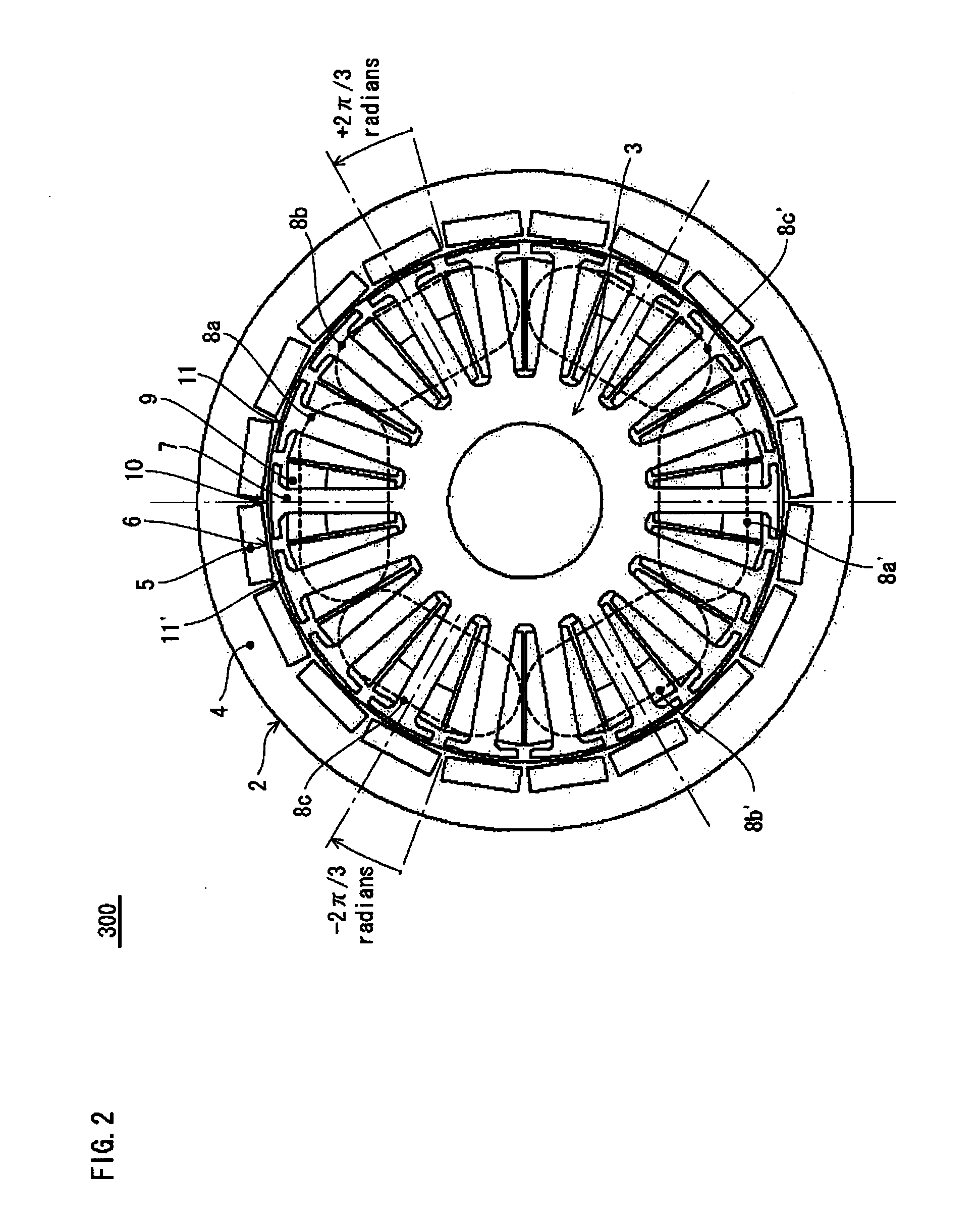
[0051]The synchronous m...
embodiment 2
[0146]FIG. 22 shows an overall structure of a synchronous motor drive system pertaining to Embodiment 2 of the present invention. The synchronous motor drive system shown in FIG. 22 has the same structure as the synchronous motor drive system shown in FIG. 1 except that the inverter group 200 and the control circuit 400 are replaced with an inverter group 220 and a control circuit 406. The following explains the differences from the synchronous motor drive system pertaining to Embodiment 1.
[0147]Three-phase inverters 221, 222 and 223 included in the inverter group 220 are different from the three-phase inverters 201, 202 and 203 pertaining to Embodiment 1 in that they have temperature sensors 61, 62 and 63, respectively.
[0148]The temperature sensors 61, 62 and 63 cyclically measure the temperatures of switching devices included in power circuits 227, 228 and 229 of the three-phase inverters, respectively. The temperature sensors 61, 62 and 63 output temperature detection signals T1,...
embodiment 3
[0174]FIG. 26 shows an overall structure of a synchronous motor drive system pertaining to Embodiment 3 of the present invention. The synchronous motor drive system shown in FIG. 26 has the same structure as the synchronous motor drive system shown in FIG. 1 except that the inverter group 200 is replaced with an inverter group 230. The following explains the differences from the synchronous motor drive system pertaining to Embodiment 1.
[0175]The inverter group 230 pertaining to this embodiment is characterized by gate drive circuits 231, 232 and 233 of the three-phase inverters.
[0176]The gate drive circuits 231, 232 and 233 have gate resistances between their corresponding power circuits 207, 208 and 209 and them. The resistance value of the gate resistance for the gate drive circuit 232, to which a gate control signal based on a 20 kHz carrier signal is input from the PWM control unit 401, is lower than the gate drive circuits 231 and 233 to which a gate control signal based on a 1...
PUM
 Abstract
Description
Claims
Application Information