
Display filter having touch input function

Inactive Publication Date: 2011-05-05
SAMSUNG CORNING PRECISION MATERIALS CO LTD
View PDF2 Cites 60 Cited by
  • Summary
  • Abstract
  • Description
  • Claims
  • Application Information

AI Technical Summary

Benefits of technology

[0015]Also provided is a display filter that can minimize the thickness of the display filter even when the display filter is provided with a touch input function.
[0016]Also provided is a display filter that can block both Ultraviolet (UV) radiation and Infrared (IR) radiation, which would otherwise have a deleterious effect on the display filter, when a display device is installed outdoors.
[0021]In the display filter according to exemplary embodiments of the invention, there are advantages in that both a filter function and a touch input function can be performed.
[0022]In addition, the display filter according to exemplary embodiments of the invention does not require additional materials for the formation of the second electrode, since the grounding electrode to ground the conductive film coating layer can function as the second electrode, so that manufacturing costs can be advantageously reduced.
[0023]Furthermore, in the display filter according to exemplary embodiments of the invention, the conductive film coating layer is formed as an electromagnetic radiation shielding layer in which the high-refractivity metal oxide layer and the metal layer are laminated on each other. With this configuration, the conductive film coating layer can perform both a touch input function and an electromagnetic radiation shielding function, thereby minimizing the thickness of the filter. Moreover, since the conductive film coating layer is formed by laminating the high-refractivity metal oxide layer and the metal layer on each other, it can advantageously block Near-Infrared (NIR) radiation and UV or IR radiation, which would otherwise have a deleterious effect on the display filter.

Problems solved by technology

Also provided is a display filter that can block both Ultraviolet (UV) radiation and Infrared (IR) radiation, which would otherwise have a deleterious effect on the display filter, when a display device is installed outdoors.

Method used


Image

  • Display filter having touch input function
  • Display filter having touch input function
  • Display filter having touch input function

Examples


Embodiment Construction

[0029]Reference will now be made in detail to various embodiments of the present invention, examples of which are illustrated in the accompanying drawings and described below. While the invention will be described in conjunction with exemplary embodiments, it will be understood that the present description is not intended to limit the invention to those exemplary embodiments. On the contrary, the invention is intended to cover not only the exemplary embodiments, but also various alternatives, modifications, equivalents and other embodiments that may be included within the spirit and scope of the invention as defined by the appended claims.

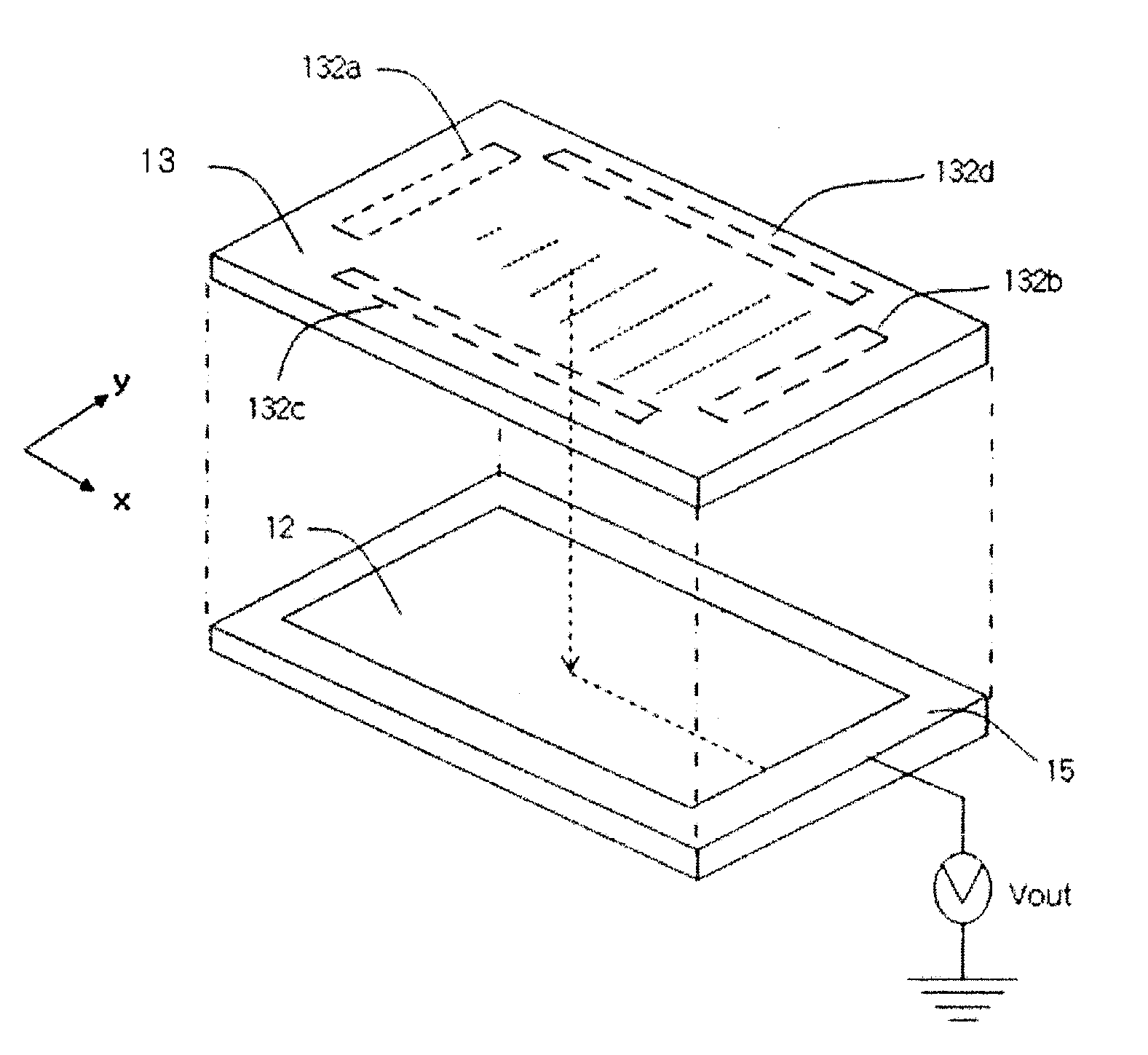
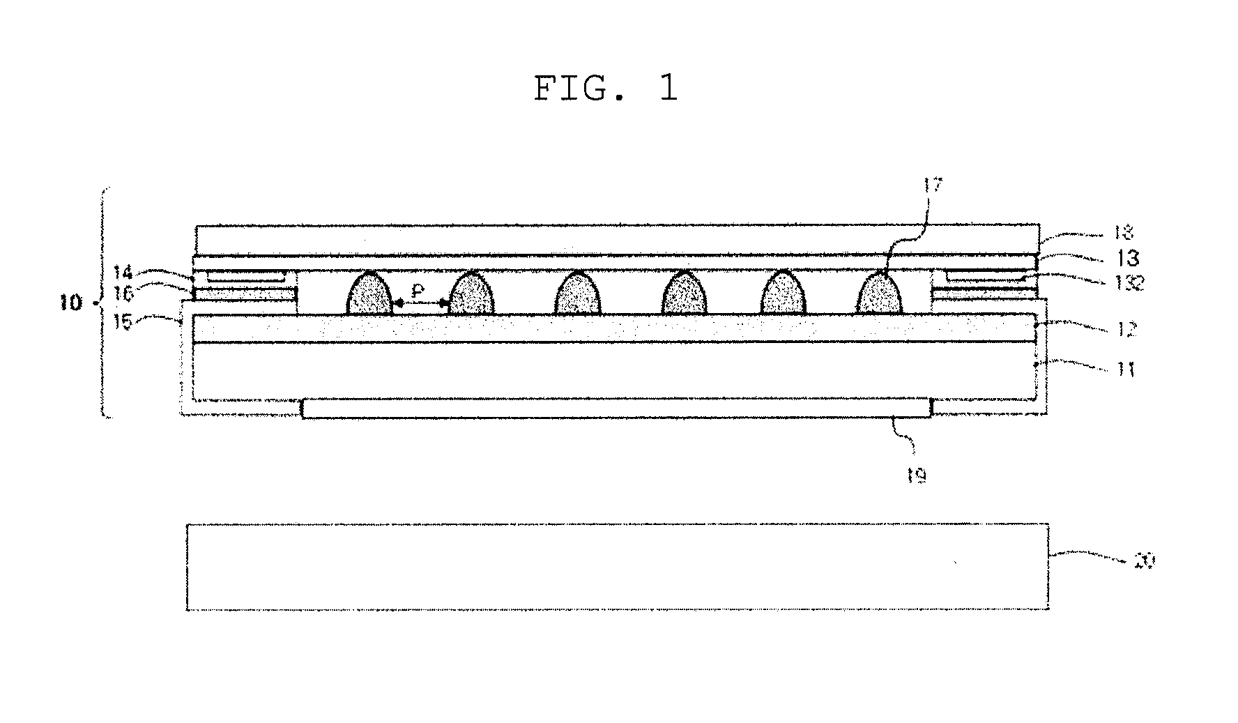
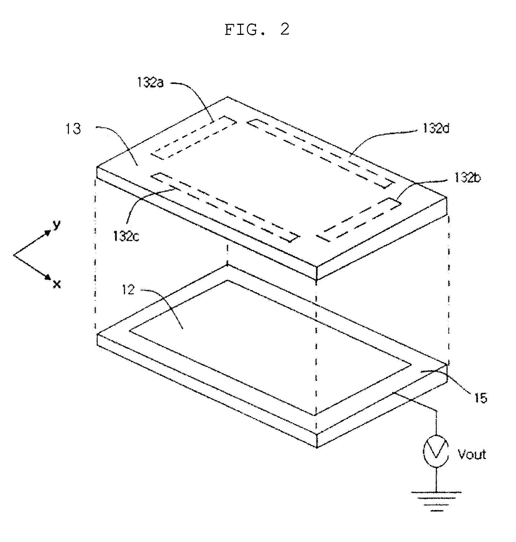
[0030]FIG. 1 is a schematic illustration of the structure of a display device to which a display filter according to an exemplary embodiment of the invention is applied, and FIG. 2 is an illustration of a touch sheet and a conductive film coating layer of the display filter according to the exemplary embodiment of the invention.

[0031]As shown in FI...


PUM


Abstract

A display filter having a touch input function includes a base substrate, a conductive film coating layer formed on the base substrate, and a touch sheet. The touch sheet and the conductive film coating layer are arranged with an air gap therebetween, and are in contact with each other in response to a touch pressure. A first electrode is formed on a surface of the touch sheet that faces the conductive film coating layer. The first electrode includes a first electrode part to which a first input voltage is applied to generate potential distribution in the x direction, and a second electrode part to which a second input voltage is applied to generate potential distribution in the y direction. A second electrode is formed on the periphery of the conductive film coating layer, and allows electrical current to flow through when the touch sheet is in contact with the conductive film coating layer.

Description

CROSS REFERENCE TO RELATED APPLICATION[0001]The present application claims priority from Korean Patent Application Number 10-2009-0103885 filed on Oct. 30, 2009, the entire contents of which application are incorporated herein for all purposes by this reference.BACKGROUND OF THE INVENTION[0002]1. Field of the Invention[0003]The present invention relates to a display filter, and more particularly, to a display filter in which information can be input by a touch operation.[0004]2. Description of Related Art[0005]In response to the advent of the information society, a variety of types of display devices has been developed. As examples of such display devices, a Liquid Crystal Display (LCD), a Plasma Display Panel (PDP), an Electro Luminescent Display (ELD), and the like have been developed.[0006]The LCD, one example of the display device, is manufactured by forming an array substrate through an array substrate fabrication process, in which Thin Film Transistors (TFTs) and pixel electro...

Claims


Application Information

Patent Timeline
IPC IPC(8): G06F3/041
CPCG06F3/045
Inventor LIM, JIN SUNGPARK, DAE CHULKIM, HONG IKKIM, SHIN WOOKKIM, HO WOO
Owner SAMSUNG CORNING PRECISION MATERIALS CO LTD
Learn More