
Waveform based bit detection for bit patterned media

a waveform and bit patterned technology, applied in the field of waveform based bit detection for bit patterned media, can solve the problems of difficult to apply the method to bpm, and difficult to maintain a consistent track between the read sensor and the writing pole on the transducer head, so as to improve the writing of data and quickly and accurately detect patterned bits on the disc.

Active Publication Date: 2011-05-05
SEAGATE TECH LLC
View PDF21 Cites 21 Cited by
  • Summary
  • Abstract
  • Description
  • Claims
  • Application Information

AI Technical Summary

Benefits of technology

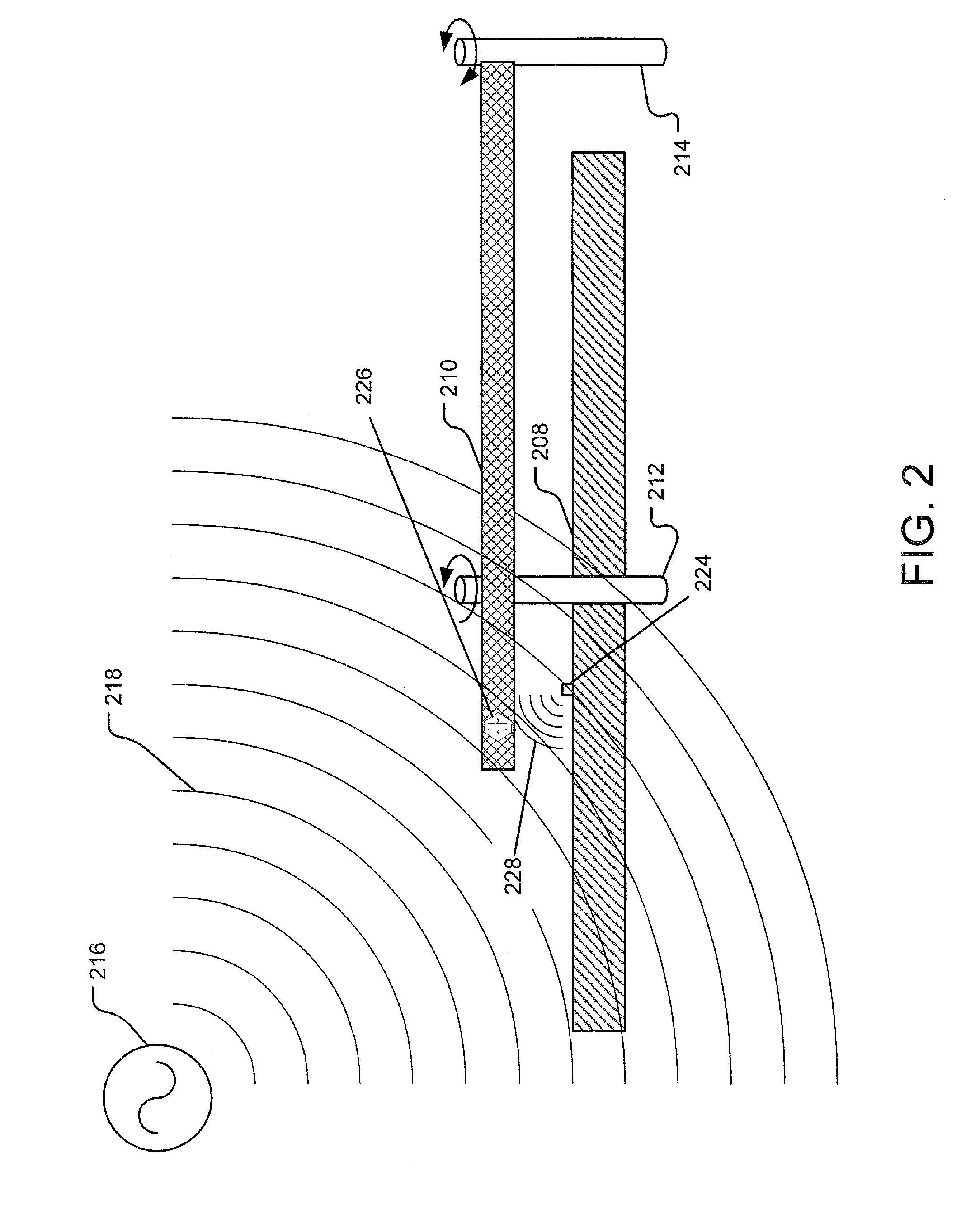
An implementation of the presently disclosed technology utilizes an oscillator to generate a waveform (e.g. microwave and infrared) that propagates in the direction of bit-patterned media (BPM) on a disc and a waveform sensor configured to detect the waveform after it is reflected from the disc. A processor relates at least one property of the reflected waveform with positions of patterned bits on the disc. This technique provides the ability to more quickly and accurately detect patterned bits on the disc to allow for improved writing of data to a hard disc drive.

Problems solved by technology

As hard disc drive areal or bit density increases, maintaining a consistent track between the read sensor and a writing pole on the transducer head becomes increasingly difficult.
Therefore, one of the challenges with BPM is placing the head over the bit of interest accurately during writing.
This is especially challenging due to the small size of the patterned bits (e.g. 1 nano-meter wide) and timing control requirements in a disc system rotating at high speeds (e.g. 20-50 pico-seconds per bit or patterned cell).
Conventionally, a transducer head uses a read-before-write process to maintain alignment on a data track; however, that method does not easily apply to BPM.

Method used


Image

  • Waveform based bit detection for bit patterned media
  • Waveform based bit detection for bit patterned media
  • Waveform based bit detection for bit patterned media

Examples


Embodiment Construction

In non-BPM magnetic storage media, a magnetic recording layer includes a thin film of a magnetic alloy that forms random nanometer-scale grains that behave as independent magnetic elements. Each written bit is made up of many of these random grains. In BPM, the magnetic layer is pre-patterned with an ordered array of patterned bits, each patterned bit capable of storing an individual data bit. The BPM may be pre-patterned through various procedures such as, but not limited to, lithography, ion-milling, etc.

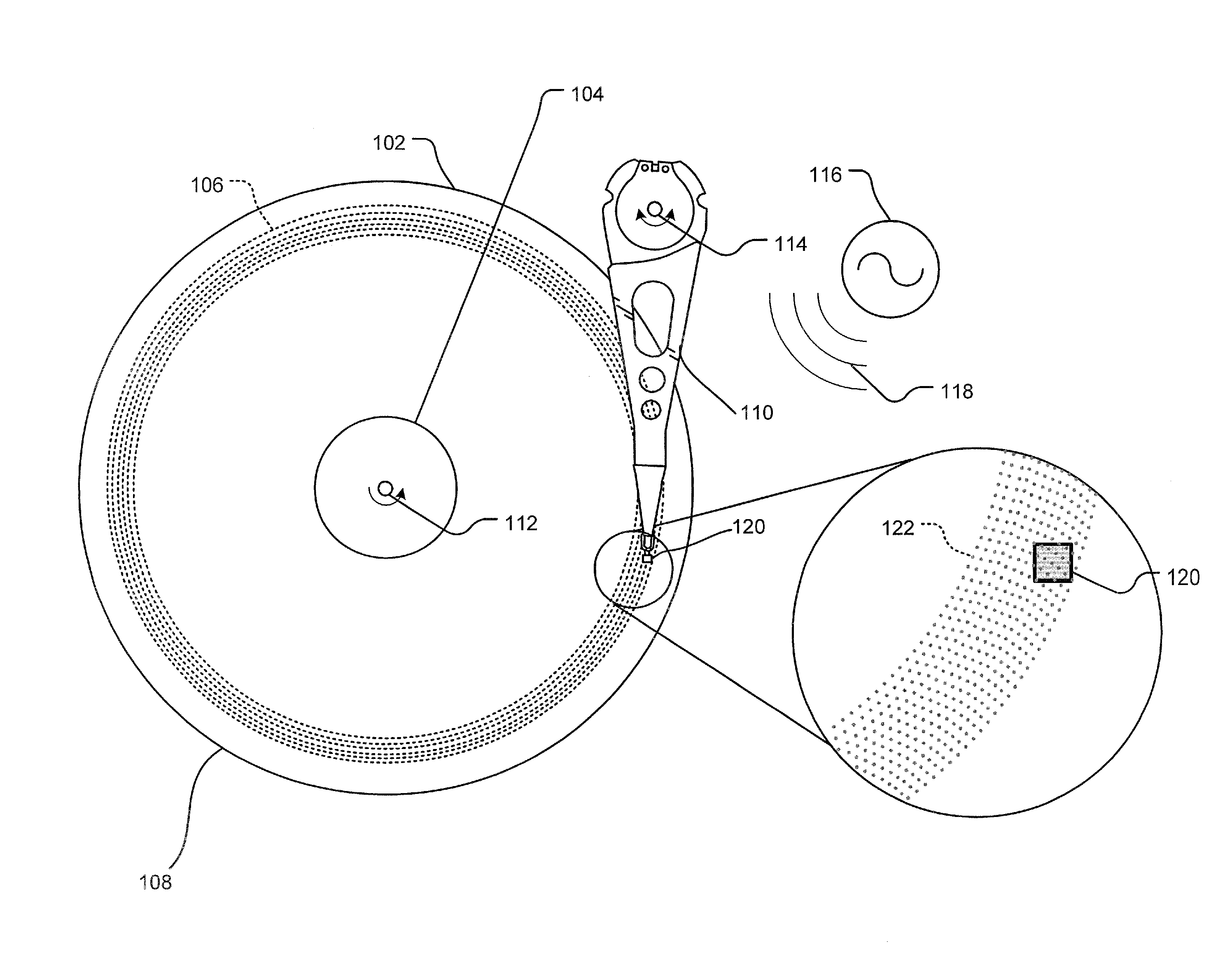
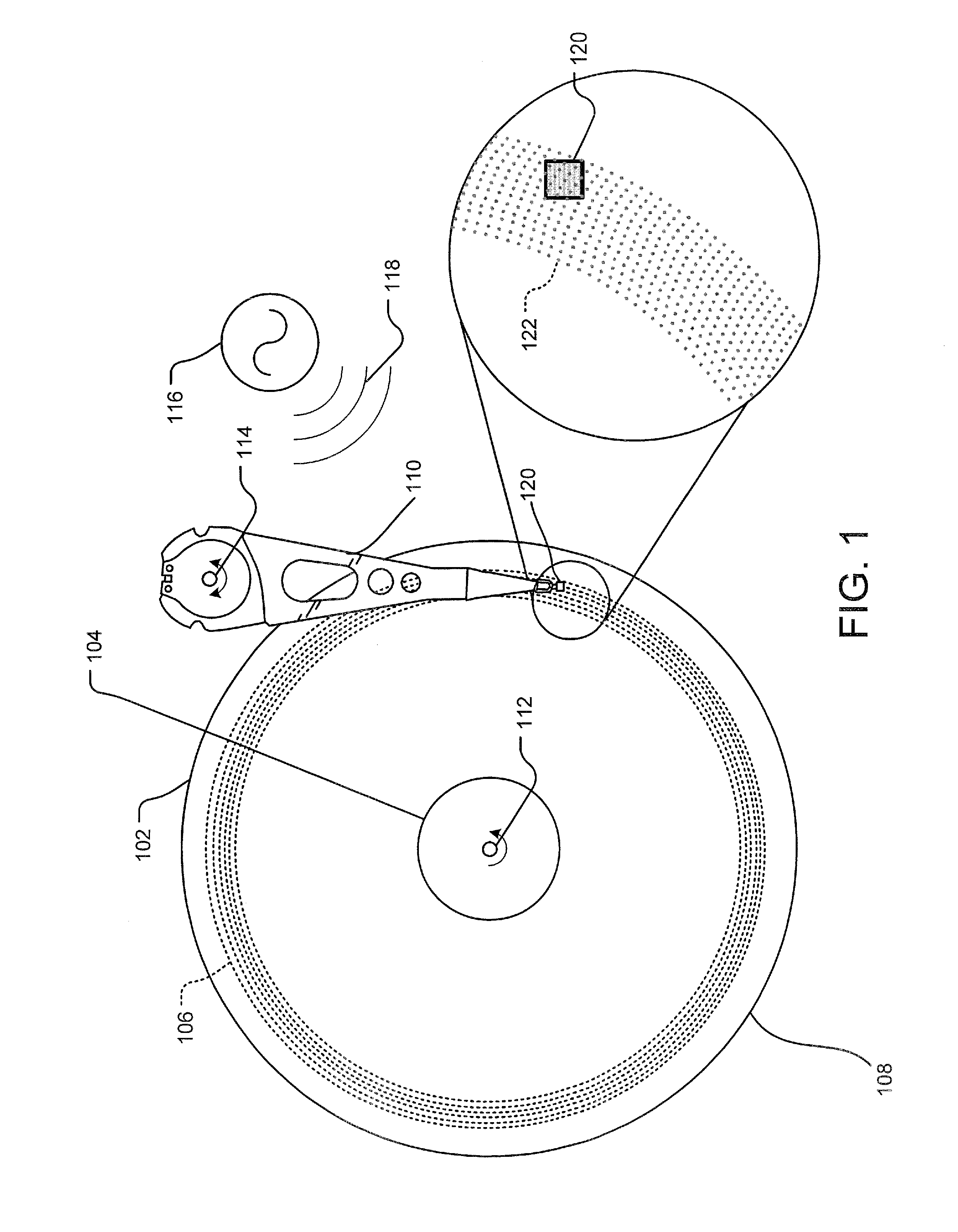
FIG. 1 illustrates a plan view of an implementation of BPM on a disc 108 with a transducer head 120 situated on an end of an actuator assembly 110. Disc 108 rotates about a disc axis of rotation 112 during operation. Further, disc 108 includes an outer diameter 102 and inner diameter 104 between which are a number of data tracks 106, illustrated by circular dotted lines. Data tracks 106 are substantially circular and are made up of regularly spaced patterned bits 122.

Information m...


PUM


Abstract

The presently disclosed technology teaches a transducer head with a read sensor, a write pole, and one or more waveform sensors attached to the transducer head. Further, a waveform propagates in the direction of a BPM and the waveform sensor is configured to detect the waveform after it is reflected from the BPM. Additionally, a spin-polarized current is influenced by the BPM and a spin angular momentum sensor detects changes in spin angular momentum of the current. Further, a processor relates at least one property of the reflected waveform and / or current with positions of patterned bits on the BPM. The processor may then modify a timing signal and / or transducer head position to ensure that data bits are accurately written to the BPM. The end result is the ability to more quickly and accurately detect the patterned bits and synchronize a position of the transducer head with the patterned bits.

Description

BACKGROUND Conventionally, during a write to a hard disc by a transducer head, the transducer head uses a magnetic read sensor to read up-track of the writing location to assure the desired data track is targeted during the write operation. As hard disc drive areal or bit density increases, maintaining a consistent track between the read sensor and a writing pole on the transducer head becomes increasingly difficult.Additionally, in the continuing effort to increase areal density, hard discs with arrays of patterned cells have been designed where each cell can hold a bit of data (bit patterned media (BPM)). With BPM, data may be stored in individual cells along a data track defined by the patterned bits. However, each patterned bit must be temporally synchronized with each data bit. Otherwise, data insertion may occur on an incorrect patterned bit or a patterned bit may be skipped for data writing. Therefore, one of the challenges with BPM is placing the head over the bit of interes...

Claims


Application Information

Patent Timeline
IPC IPC(8): G11B5/02
CPCB82Y10/00G11B5/09G11B2005/001G11B5/743G11B5/59616
Inventor JOHNSTON, ALAN BIGGARWELLER, DIETER KLAUSGUBBINS, MARK ANTHONY
Owner SEAGATE TECH LLC
Learn More