
Spin valve element, method of driving the same, and storage device using the same

Active Publication Date: 2011-05-05
III HLDG 3
View PDF10 Cites 4 Cited by
  • Summary
  • Abstract
  • Description
  • Claims
  • Application Information

AI Technical Summary

Benefits of technology

[0024]According to any one of the embodiments of the invention, it is possible to provide a multi-value recordable spin valve element having at least one effect such as achievement of high recording density without using a complicated structure such as multiple structures and realization of a spin valve element capable of performing multi-value recording with use of a unipolar pulse at the time of using spin injection magnetization reversal. In addition, it is possible to implement a storage device using such a spin valve element.

Problems solved by technology

However, since the conventional multi-value recording technology still involves several problems, it has not yet come to the practicable stage.
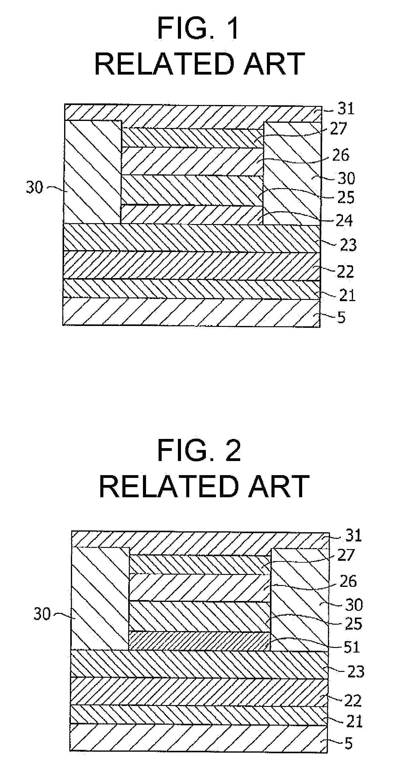
For this reason, in the solid state magnetic memory disclosed in JP-A No. 10-91925, if a magnetoresistance ratio of at least one of the two multi-layered structures included in the solid state magnetic memory is configured not to be larger than a magnetoresistance ratio of a TMR element having a single-tunnel junction of a structure including a ferromagnetic layer / a non-magnetic layer / a ferromagnetic layer (the other TMR type element), there is a problem in that a sufficient S / N ratio cannot be obtained.
However, this method is disadvantageous in that it requires multiple structures and it needs to perform a switching operation with use of the external magnetic field by generating two directional magnetic fields (forward and backward) for each ferromagnetic layer, that is, generating a total of four directional magnetic fields.
However, this technique has a problem with an increased area in the lateral direction due to the area occupied by the standby portions.
For such a reason, although the multi-value recording is achieved, the improvement of the recording density is unsuccessful.
However, this technique has a problem in that achievement of the shape anisotropy leads to warping of a shape (distortion) and an increase in the reversal magnetic field.
However, according to this disclosure, since the arrangement of the “defects” serving as recoding points is limited to the linear fashion, practically it is difficult to increase the density of the recording points.
In addition, Rahm et al. does not disclose a configuration of a spin valve element having a simple reading function.

Method used


Image

  • Spin valve element, method of driving the same, and storage device using the same
  • Spin valve element, method of driving the same, and storage device using the same
  • Spin valve element, method of driving the same, and storage device using the same

Examples


Embodiment Construction

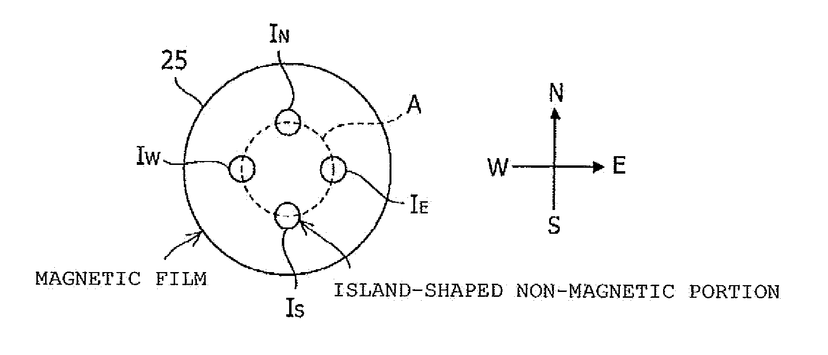
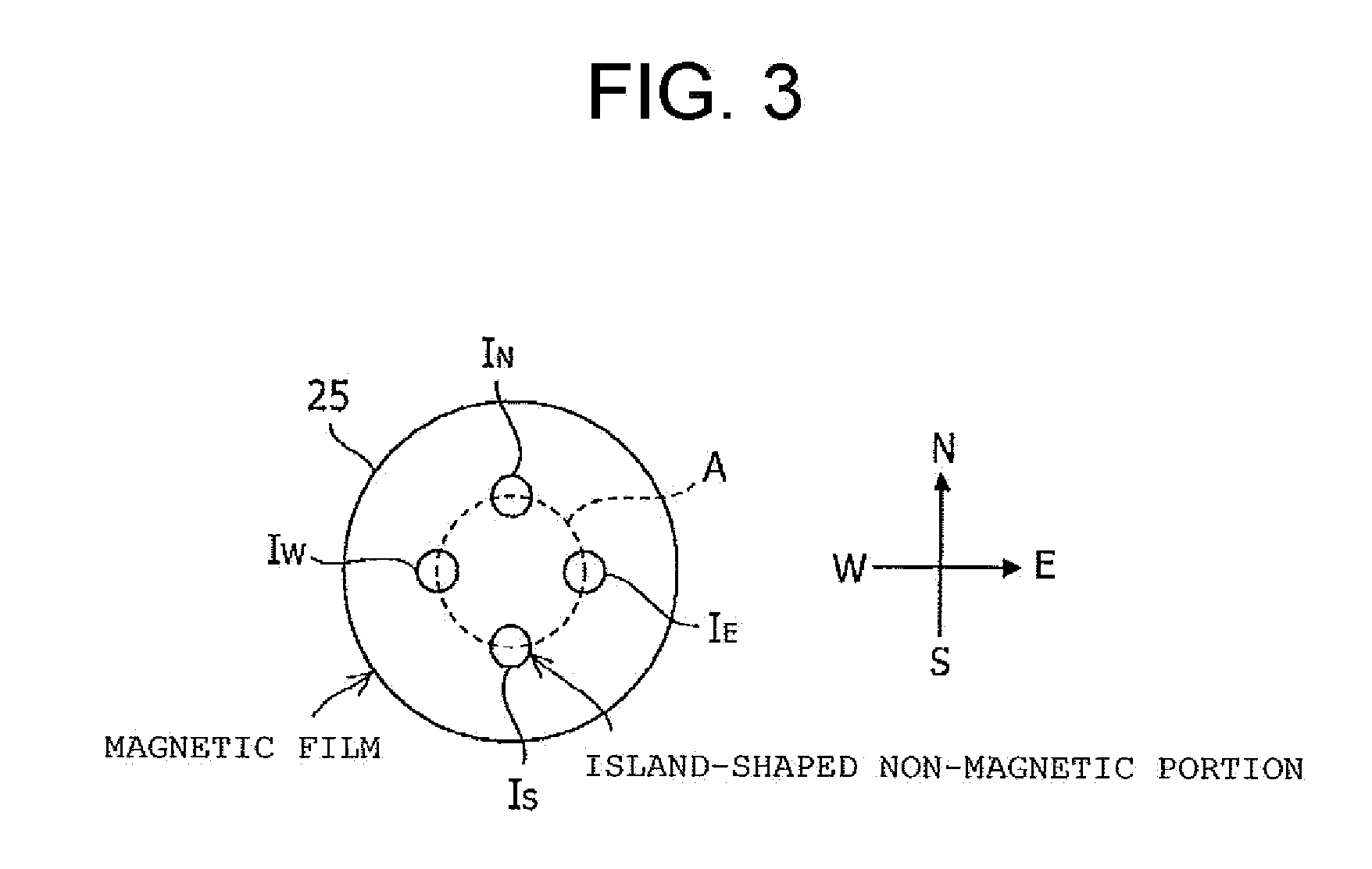
[0037]In a spin valve element according to the invention, an in-plane profile of the spin valve element is configured to be substantially circular, and plural island-shaped non-magnetic areas (hereinafter, referred to as island-shaped non-magnetic portions) are formed on the in-plane. With the structure in which the in-plane profile is configured to be substantially circular and plural island-shaped non-magnetic portions are provided, in the spin valve element according to the invention, it is possible to reduce a shape anisotropy at the time of writing thereby to decrease a recording magnetic field and to realize a state in which vortexes of a magnetization pattern in the in-plane of a free layer is pinned at any of island-shaped dots pr at a certain number of island-shaped dots.

[0038]In this manner, multi-value recording can be implemented in the spin valve element according to the invention. According to such a configuration, a number of stabilized states as many as the number of...


PUM


Abstract

Provided is a spin valve element capable of performing multi-value recording, which includes a pair of ferromagnetic layers having different coercivities from each other, and sandwiching an insulating layer or a non-magnetic layer. The ferromagnetic layer having the smaller coercivity has a substantially circular in-plane profile, and a plurality of island-shaped non-magnetic portions IN, IE, IW, and IS are included. In addition, a storage device is manufactured by using such a spin valve element.

Description

CROSS-REFERENCE TO RELATED APPLICATIONS[0001]This application is a national stage application under 35 U.S.C. §371 of International Application No. PCT / JP2008 / 66076, filed Sep. 5, 2008, and claims the benefit under 35 U.S.C. §119 of the earlier filing date of Japanese Patent Application 2008-182651, filed Jul. 14, 2008. International Application No. PCT / JP2008 / 66076 and Japanese Patent Application 2008-182651 are hereby incorporated herein in their entirety by reference.TECHNICAL FIELD[0002]The present invention relates to a spin valve element capable of writing and reading information by controlling distribution of magnetization of a ferromagnetic layer, a method of driving the same, and a storage device using the same.BACKGROUND ART[0003]In the related art, with recent progress in nano-electronics, products utilizing physical phenomena inherent in minute-sized magnetic materials have been developed. Particularly developments are rapid in the technical fields using the spin of free...

Claims


Application Information

Patent Timeline
IPC IPC(8): G11B5/82G11B5/012
CPCB82Y25/00G01R33/093G11C11/16H01F10/3254H01F10/325H01F10/3286G01R33/098H01L43/08G11C11/161G11C11/1673G11C11/1675G11C11/5607H10N50/10
Inventor KAWAKAMI, HARUOOGIMOTO, YASUSHI
Owner III HLDG 3
Learn More