Devices for clearing blockages in in-situ artificial lumens

a technology of artificial lumens and devices, which is applied in the direction of wound drains, applications, catheters, etc., can solve the problems of gj- and j-tube obstructions that are difficult to clear, gj- and j-tube obstructions are particularly difficult, and the standard nursing protocol to clear occlusions is time-consuming at best and is often unsuccessful

Active Publication Date: 2011-05-05
ACTUATED MEDICAL
View PDF78 Cites 98 Cited by
  • Summary
  • Abstract
  • Description
  • Claims
  • Application Information

AI Technical Summary

Benefits of technology

[0086]FIG. 29E is a partial isometric view of the distal end of the sheath of the tube clearers TC1 and TC2 showing a small sheath channel for a very narrow hollow wire and a larger channel for aspiration / irrigation.

Problems solved by technology

Reported clogging rates of GJ and J-tubes have been as high as 35% mainly due to the small bore, considerable length, and convoluted geometries of the tubes once placed.
As the discussion below suggests, standard nursing protocols to clear tube occlusions are time consuming at best and are often unsuccessful.
GJ- and J-tubes are especially challenging due to the curvature associated with placement.
When a patient's enteral feeding tube becomes clogged, the process of clearing it can be time-consuming and expensive, especially if the tube must be replaced.
Additionally, a clog can interrupt the patient's supply of nutrients and cause him discomfort.
Small-bore tubes are even more prone to clogging than are large-bore tubes, and clogging of these tubes has been shown to be a major cause of feeding downtime.
A patient with an occluded tube may miss several hours of feeding and receiving nutrients before the tube is unclogged or replaced.
Over time, feeding tubes become brittle and need to be replaced.
A major cause of this is the accumulation of fungus inside the feeding tube.
Standard feeding tube maintenance is to “flush” feeding tubes with water; however, this does not remove debris and fungus from the inner walls.
Once a tube clogs, it is prone to reclogging.
Certain medications, such as Metamucil or liquid pain reliever, build up on the inner walls of the tube and promote clogging.
If these medications are not adequately flushed or crushed finely, they will clog the tube.
Due to medical restrictions on fluid intake, or if the care-giver is rushed, an adequate flush may not occur.
A clogged tube can leave an already compromised patient without medication or nutrition for hours, or even days, and is extremely frustrating to both the patient and the caregiver.
While this is certainly positive, the down side is that when a feeding tube becomes clogged such that it cannot be unclogged with conventional methods, the patient must be transported to a specialty hospital to have the tube surgically removed and replaced.
For persons recovering in rural areas, this could be even more problematic as an extensive car ride—several hours—may be necessary to reach the specialty hospital.
This disruption is a time consuming, expensive, and agonizing experience for the patient and family members.
Numerous hours without nutrients and medication could have significant adverse effects on recovery of wounded soldiers, elderly and chronically ill patients.
While the solution provides some assistance in degrading the clogged matter, some patients may be allergic to at least one of these ingredients and the system for introducing the chemical solution is not always successful.
However, this may not always be done with enough efficiency or regularity and a high percentage of tubes remain clogged.
Chemical approaches to clog removal are not effective.
Patients can also be allergic to the ingredients in the chemical approaches, or adversely affected by the high sodium content.
Tiny brushes on wires can be used to break up the clog, but have been reported to pack the material in some clogs even more densely.
Even when successful, these approaches can take up to 30 minutes to several hours per patient, do not leave the tube walls clear, and do not progress through tortuous paths well.

Method used


Image

  • Devices for clearing blockages in in-situ artificial lumens
  • Devices for clearing blockages in in-situ artificial lumens
  • Devices for clearing blockages in in-situ artificial lumens

Examples


Embodiment Construction

[0087]The preferred embodiments of this present invention are illustrated in FIGS. 1-29E with the numerals referring to like and corresponding parts.

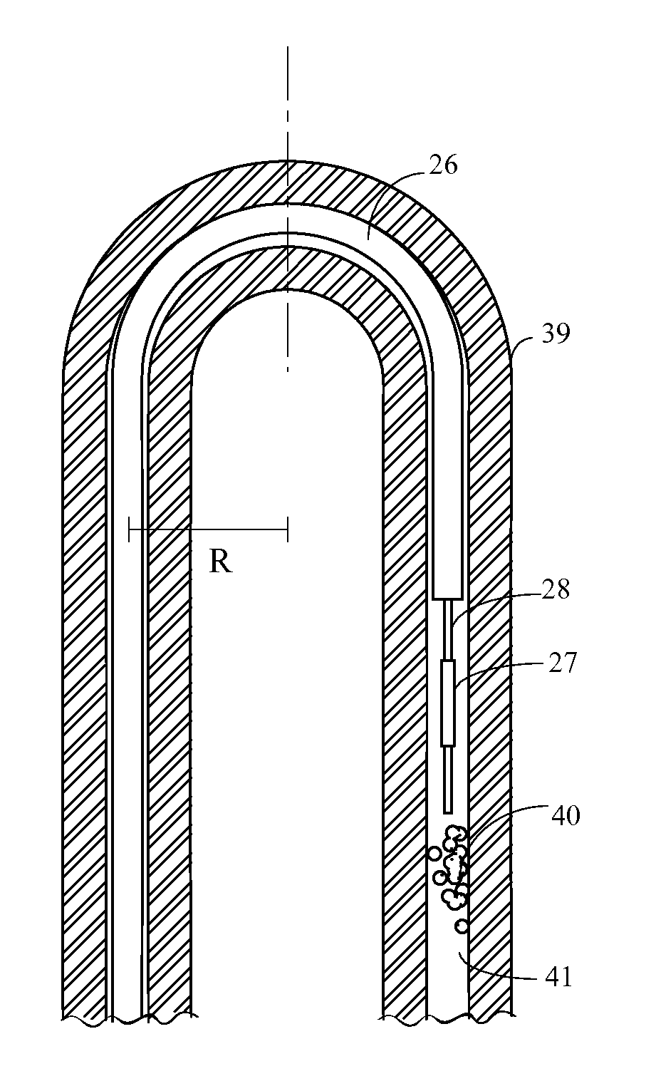
[0088]The present inventions are portable devices, as well as methods for such devices, for effectively removing, moving or breaking up a clog from the internal portions of an artificial tube or catheter, enteral tube, and preferably a feeding tube, including pediatric feeding tubes. The action of removing clogs and clearing artificial tubes can also be referred to as a “maintenance action”.

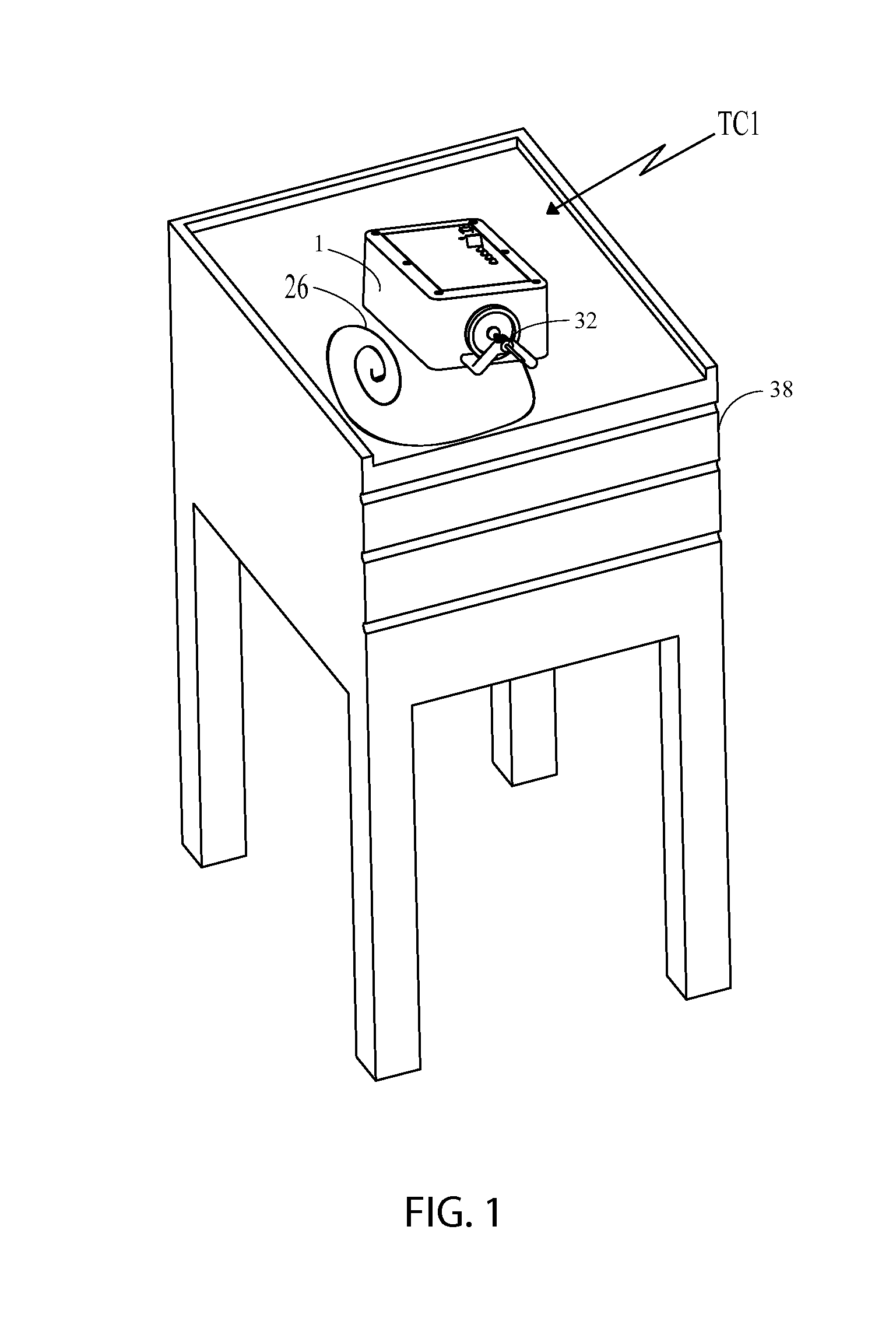
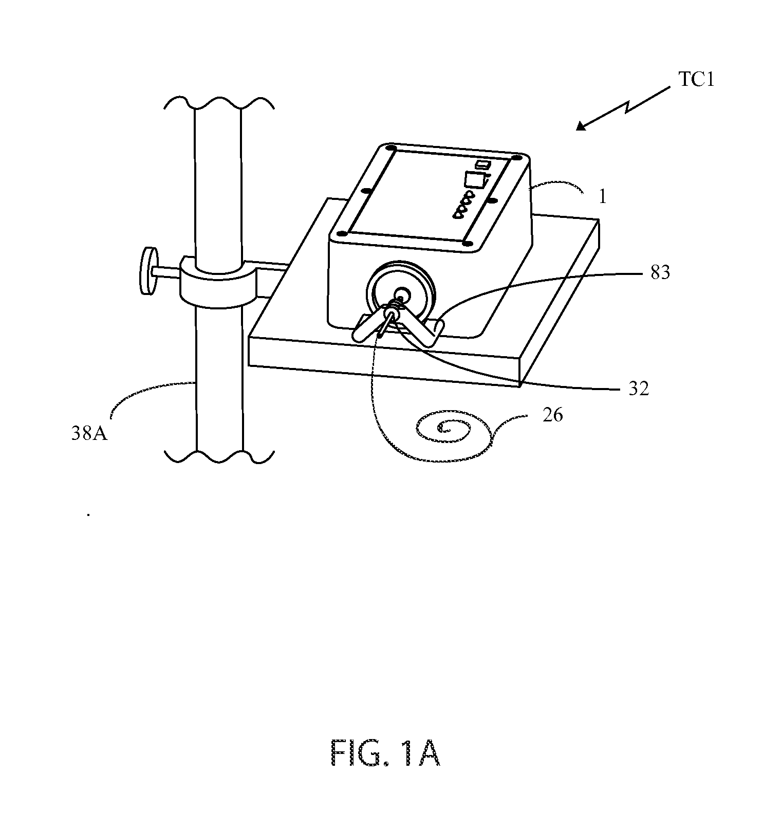
[0089]As will be discussed in detail later, there are basically two types of tube clearers (TC) disclosed herein, both of which are mechanical tube clearers. The first type of tube clearer TC1 includes several embodiments that generate reciprocating motion of a clearing member for removing, moving or otherwise breaking up a clog in the artificial tube. This tube clearer TC1 is preferred for use in nastrogastic (NG) feeding tubes, although it should b...


PUM


Abstract

Devices and methods for the effective clearing of artificial tubes, especially in-situ clearing of artificial tubes in a living being are covered in this disclosure. The devices and methods provide an elongated clearing member having a first end that is coupled to a driving mechanism and having a second working end that is subjected to repetitive motion for clearing blockages within the artificial tube. The elongated clearing member includes either a fixed or an adjustable element that selectively defines the portion of the elongated clearing member that is insertable within the artificial tube. The proximal end of the clearing member is releasably secured to the driving mechanism and the driving mechanisms may comprise a wide variety of repetitive motion drivers such as voice coil motors, piezoelectric actuators, pneumatic actuators, DC motors, etc. These devices/methods may comprise a free-standing console for hands-free operation or may comprise hand-held versions. The distal working end of the clearing member may comprise tips of differing functions, including an irrigation/aspiration feature.

Description

CROSS-REFERENCE TO RELATED APPLICATIONS[0001]This continuation-in-part application claims the benefit under 35 U.S.C. §120 of U.S. application Ser. No. 12 / 274,937, filed on Nov. 20, 2008 entitled FEEDING TUBE CLEANER which in turn claims the benefit under 35 U.S.C. §119(e) of U.S. Provisional Patent Application No. 60 / 989,484, filed on Nov. 21, 2007 entitled FEEDING TUBE CLEANER and of U.S. Provisional Patent Application No. 61 / 099,737, filed on Sep. 24, 2008 entitled DEVICE FOR CLEARING BLOCKAGES IN FEEDING TUBES and all of whose entire disclosures are incorporated by reference herein.STATEMENT REGARDING FEDERALLY SPONSORED RESEARCH OR DEVELOPMENT[0002]This invention was produced in part using funds from the Federal government under National Science Foundation Award ID nos. IIP-0810029 and IIP-0923861. Accordingly, the Federal government may have certain rights in the invention.BACKGROUND OF THE INVENTION[0003]1. Field of Invention[0004]The present invention generally pertains to c...

Claims


Application Information

Patent Timeline
Patent Type & Authority Applications(United States)
IPC IPC(8): A61M39/00
CPCA61M2025/0019B08B9/0436A61J15/00A61M25/00A61J15/0026A61B19/34A61M1/0078A61B2019/343A61B1/018B08B9/027A61B90/70A61B2090/701Y10T137/789Y10T137/6055A61M1/83
Inventor BAGWELL, ROGER B.FRANKHOUSER, PAUL L.MULVIHILL, MAUREEN L.CRESPO, JOSUEPARK, BRIAN M.MALLEN, DANA B.MEZA, GABRIELA HERNANDEZDEMERS, DEBORA L.
Owner ACTUATED MEDICAL
Why Eureka
Try Eureka