Reducing agent injection valve abnormality detection device and abnormality detection method

a technology of reducing agent and injection valve, which is applied in the direction of mechanical equipment, machines/engines, electric control of exhaust treatment, etc., can solve the problems of reducing the purification efficiency of exhaust gas, clogging of the reducing agent injection valve, and insufficient purification catalyst, etc., and achieve the effect of eliminating clogging

Inactive Publication Date: 2011-05-12
BOSCH CORP
View PDF12 Cites 49 Cited by
  • Summary
  • Abstract
  • Description
  • Claims
  • Application Information

AI Technical Summary

Benefits of technology

[0043]Consequently, control for correcting the injection quantity of the reducing agent and eliminating clogging can be performed in response to the extent of clogging of the reducing agent injection valve, and whether or not the reducing agent injection valve needs to be replaced can be appropriately judged.
[0044]Further, in the reducing agent injection valve abnormality detection device of the present invention, the clogging determination component determines beforehand whether or not complete clogging is occurring in the reducing agent injection valve and thereafter determines the extent of clogging of the reducing agent injection valve when complete clogging is not seen, so that when complete clogging is occurring in the reducing agent injection valve, the clogging determination component can speedily stop reducing agent injection control or prompt replacement of the reducing agent injection valve.

Problems solved by technology

Further, sometimes, regardless of the type of reducing agent, clogging of the reducing agent injection valve occurs as a result of particulate matter of soot or the like or unburned fuel included in the exhaust gas entering the inside of the reducing agent injection valve and carbonizing.
When clogging occurs in the reducing agent injection valve, it becomes difficult to inject a target quantity of the reducing agent into the inside of the exhaust pipe, the quantity of the reducing agent that should be supplied to the NOx purification catalyst becomes insufficient, and exhaust gas purification efficiency ends up deteriorating.
Additionally, when the extent of clogging differs, a difference will arise in the quantity of reducing agent that is injected from the reducing agent injection valve in a predetermined open valve time period.
That is, the clogging determination methods of JP-A-2008-180193 and JP-A-2008-202469 can obtain a rough determination effect of determining whether or not clogging is occurring, but they cannot obtain a fine determination effect of determining the extent to which clogging is occurring.
Consequently, when the extent of clogging cannot be accurately determined, it becomes difficult to accurately perform correction of the injection quantity of the reducing agent due to clogging, and, as a result, the deterioration in exhaust gas purification efficiency until clogging is eliminated becomes unable to be kept to a minimum.
Further, when the extent of clogging cannot be determined, it becomes difficult to judge what action should be taken thereafter in response to the extent of clogging, such as whether the reducing agent injection valve should be replaced or whether the clogging can be addressed with injection quantity correction.

Method used


Image

  • Reducing agent injection valve abnormality detection device and abnormality detection method
  • Reducing agent injection valve abnormality detection device and abnormality detection method
  • Reducing agent injection valve abnormality detection device and abnormality detection method

Examples


first embodiment

[0060]A first embodiment is a reducing agent injection valve abnormality detection device for detecting,

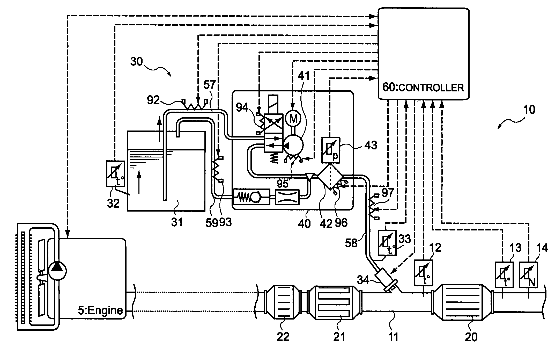
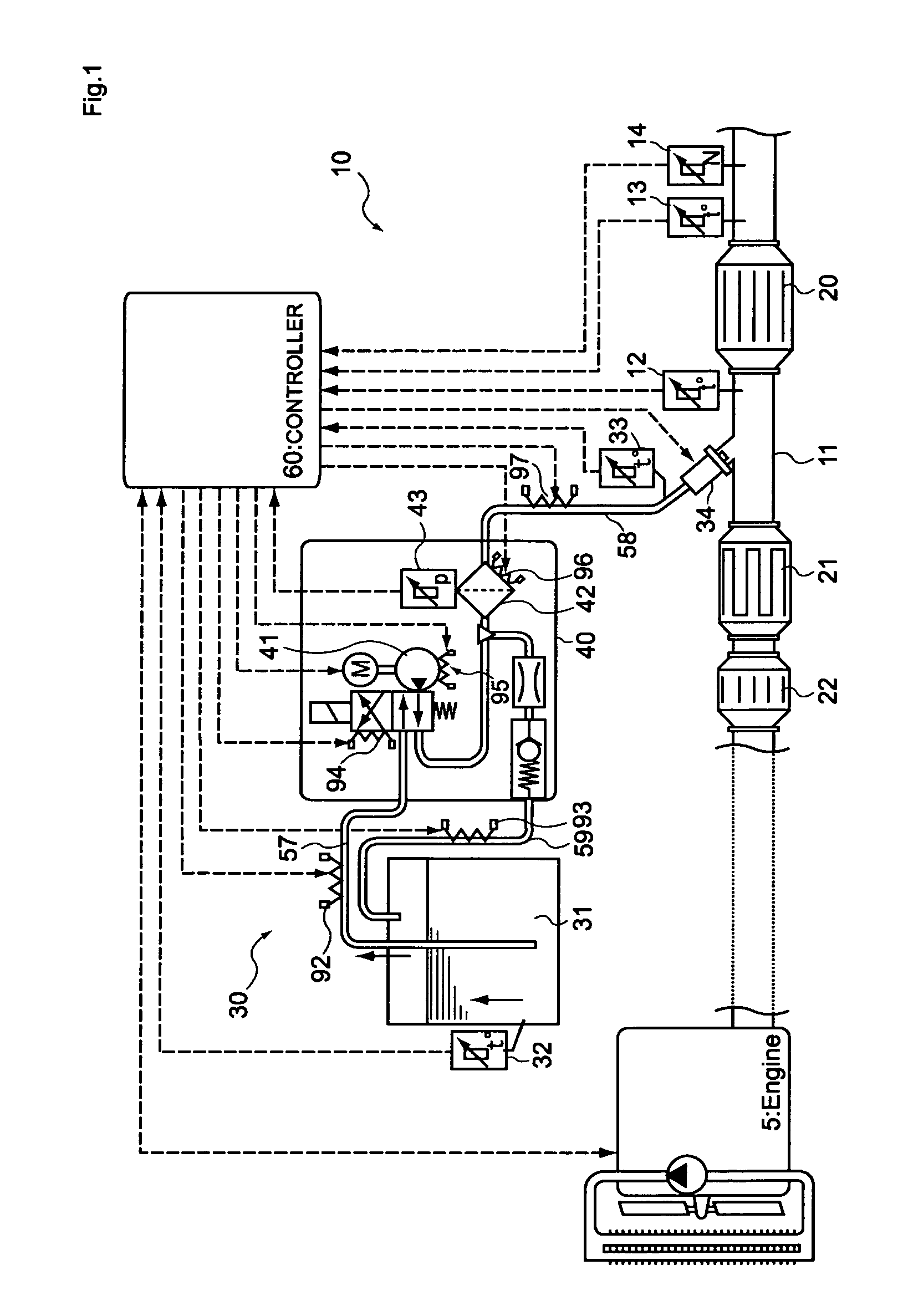
[0061]in a reducing agent injection device equipped with a storage tank that houses a reducing agent, a pump that pressure-feeds the reducing agent, a reducing agent injection valve that injects the reducing agent pressure-fed by the pump into the inside of an exhaust pipe of an internal combustion engine, a supply path that interconnects the pump and the reducing agent injection valve, and a pressure sensor that is disposed in the supply path,[0062]clogging of the reducing agent injection valve,[0063]the reducing agent injection valve abnormality detection device including:

[0064]a pressure detection component that detects the pressure inside the supply path on the basis of a sensor value of the pressure sensor;

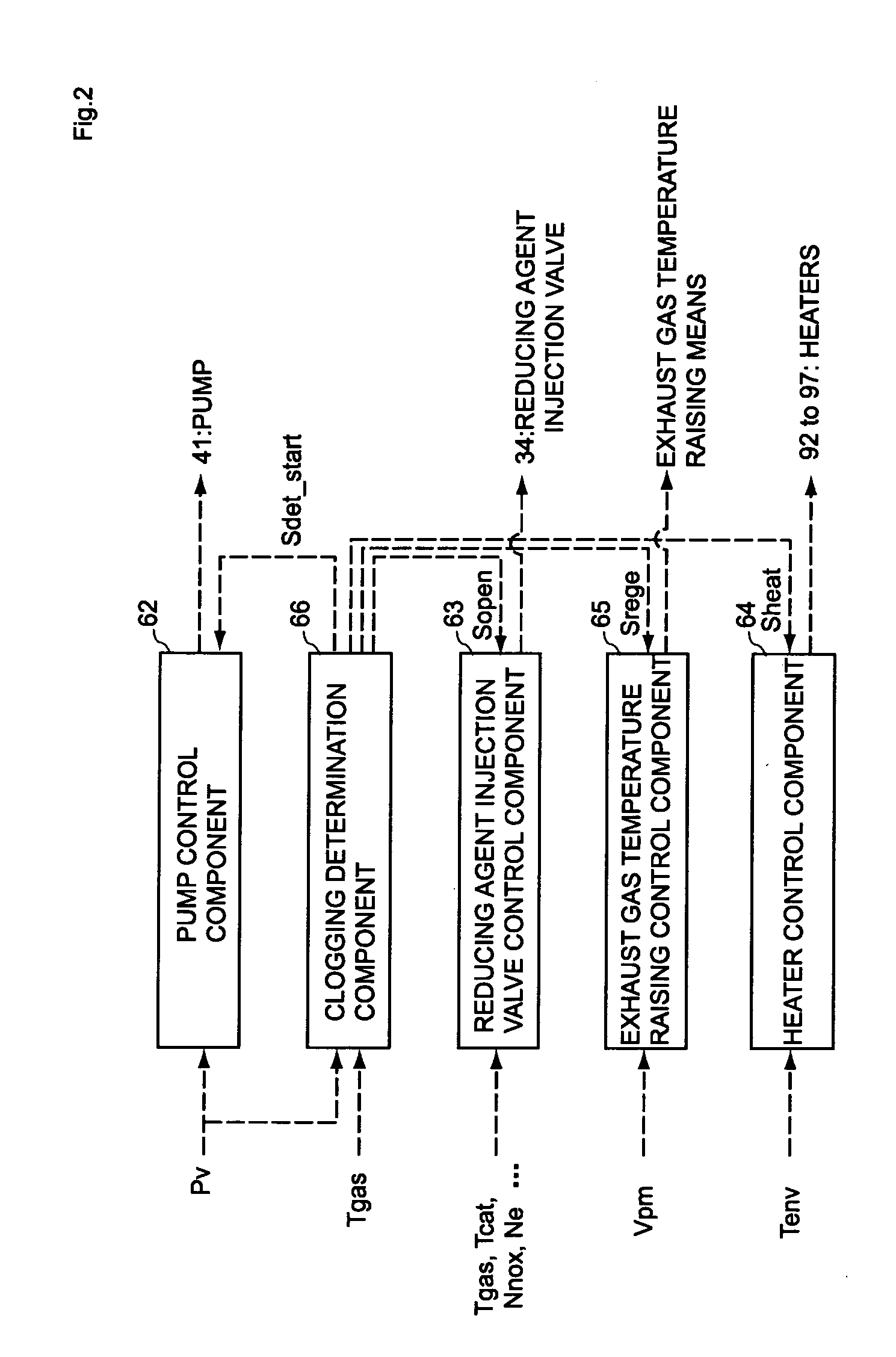
[0065]a pump control component that fixes the output of the pump in a state where the pressure inside the supply path has become a value in a predetermined range;

[0066]a re...

second embodiment

[0131]A reducing agent injection valve abnormality detection device and abnormality detection method pertaining to a second embodiment are configured to perform determination of whether or not some kind of clogging is occurring in the reducing agent injection valve before determining the extent of clogging of the reducing agent injection valve that has been described in the first embodiment.

[0132]That is, the second embodiment is a reducing agent injection valve abnormality detection method for detecting,

[0133]in a reducing agent injection device equipped with a storage tank that houses a reducing agent, a pump that pressure-feeds the reducing agent, a reducing agent injection valve that injects the reducing agent pressure-fed by the pump into the inside of an exhaust pipe of an internal combustion engine, a supply path that interconnects the pump and the reducing agent injection valve, and a pressure sensor that is disposed in the supply path,[0134]clogging of the reducing agent in...


PUM


Abstract

A reducing agent injection valve abnormality detection device for detecting clogging of a reducing agent injection valve in a reducing agent injection device has a pressure detection component that detects the pressure inside a supply path based on a sensor value of a pressure sensor, a pump control component that fixes the output of a pump in a state where the pressure inside the supply path has become a value in a predetermined range, a reducing agent injection valve control component that opens the valve for a predetermined amount of time in a state where the output of the pump has been fixed, and a clogging determination component that determines the extent of clogging of the reducing agent injection valve by comparing, with plural threshold values, the pressure, or a pressure drop quantity, inside the supply path when the valve has been opened for the predetermined amount of time.

Description

BACKGROUND[0001]1. Technical Field[0002]The present invention relates to an abnormality detection device and an abnormality detection method for detecting abnormality of a reducing agent injection valve.[0003]The present invention particularly relates to an abnormality detection device and an abnormality detection method for detecting predetermined clogging phenomena occurring in a reducing agent injection valve that injects a reducing agent for purifying nitrogen oxides in exhaust gas into the inside of an exhaust pipe.[0004]2. Related Art[0005]Conventionally, nitrogen oxides (NOx) are included in exhaust gas exhausted from internal combustion engines of automobiles and the like. As one exhaust gas purification system that reduces and purifies the NOx, there is an exhaust gas purification system configured such that a NOx purification catalyst is disposed in an exhaust pipe of an internal combustion engine and a reducing agent such as an aqueous solution of urea or unburned fuel is...

Claims


Application Information

Patent Timeline
Patent Type & Authority Applications(United States)
IPC IPC(8): F01N11/00F01N3/10
CPCF01N3/208F01N11/00F01N2550/05F01N2560/06Y02T10/24F01N2610/144F01N2900/12F01N2900/1808Y02T10/47F01N2610/10Y02T10/12Y02T10/40
Inventor IGARASHI, HIROYUKINAKAO, EIJI
Owner BOSCH CORP
Why Eureka
Try Eureka