

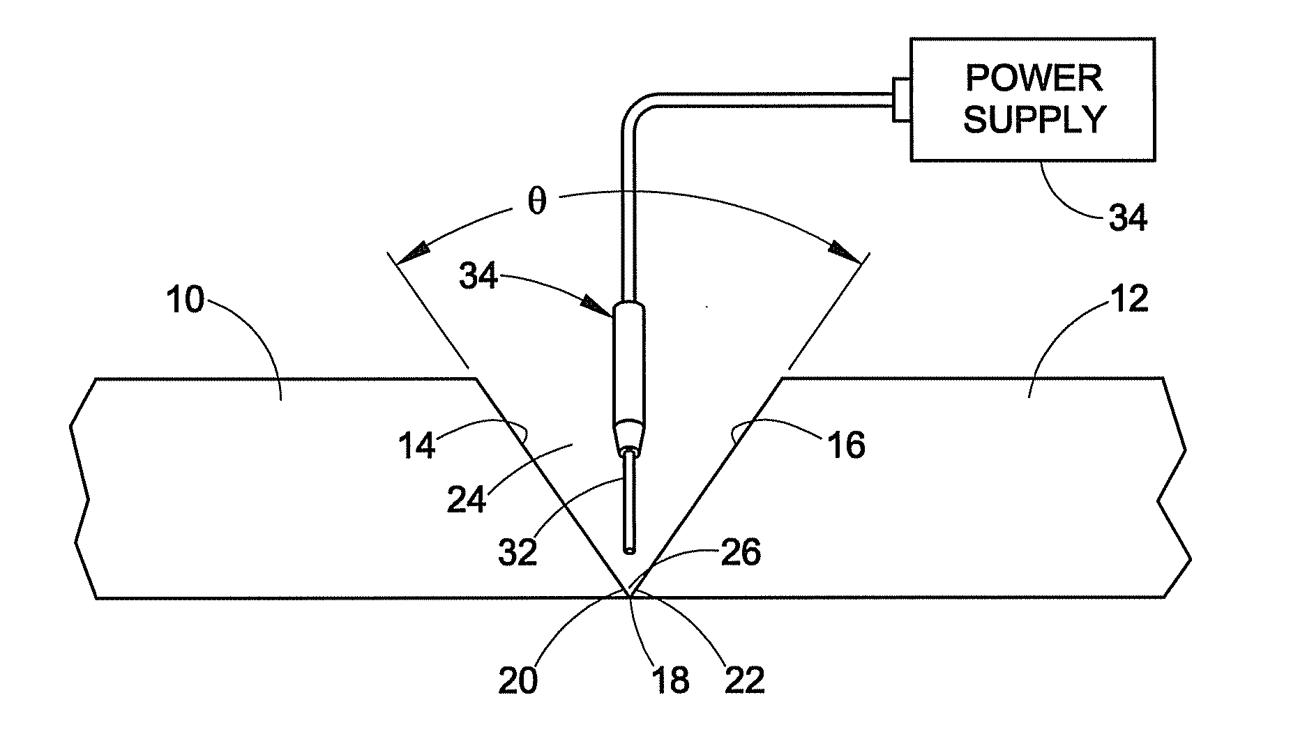
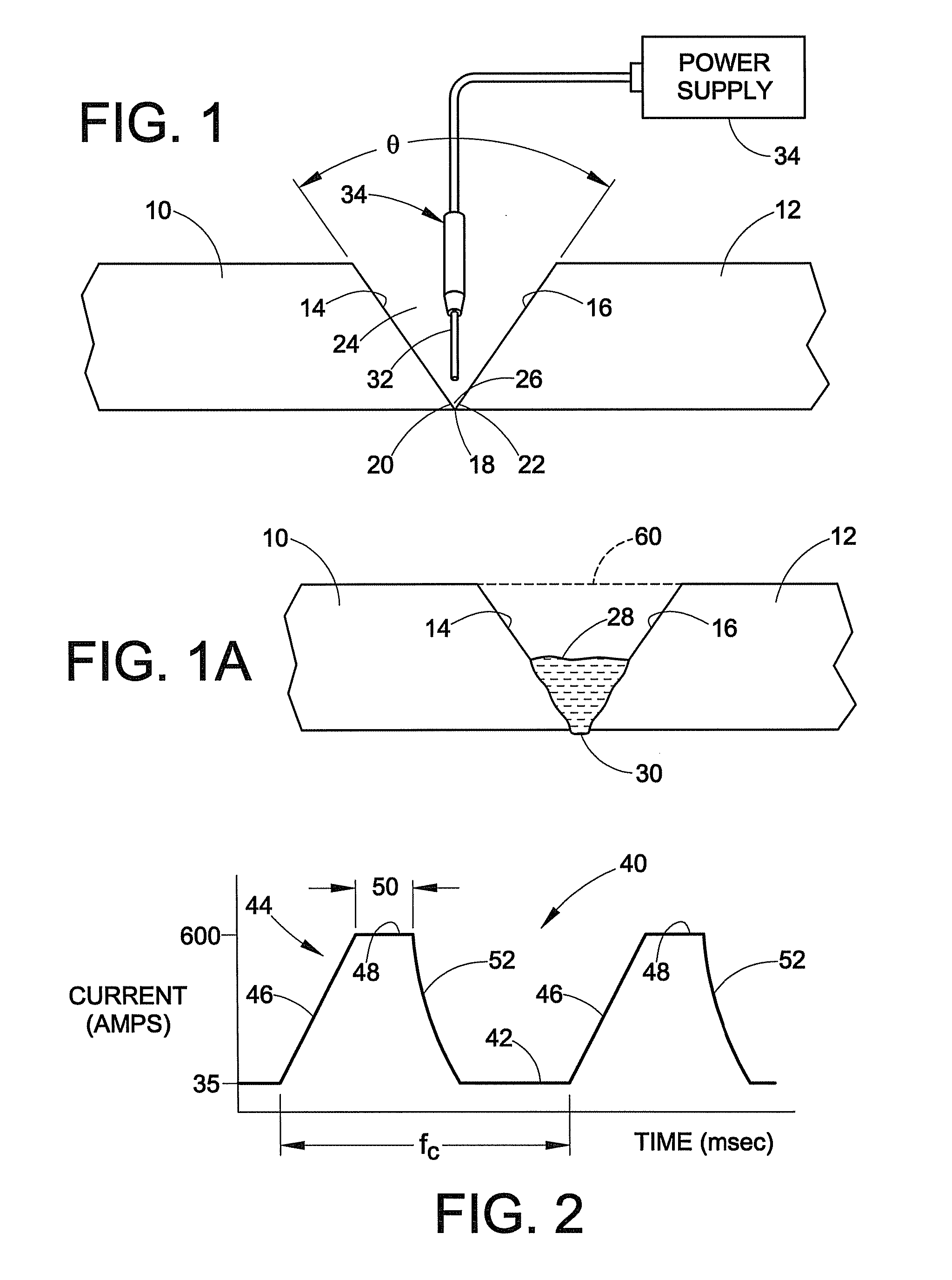
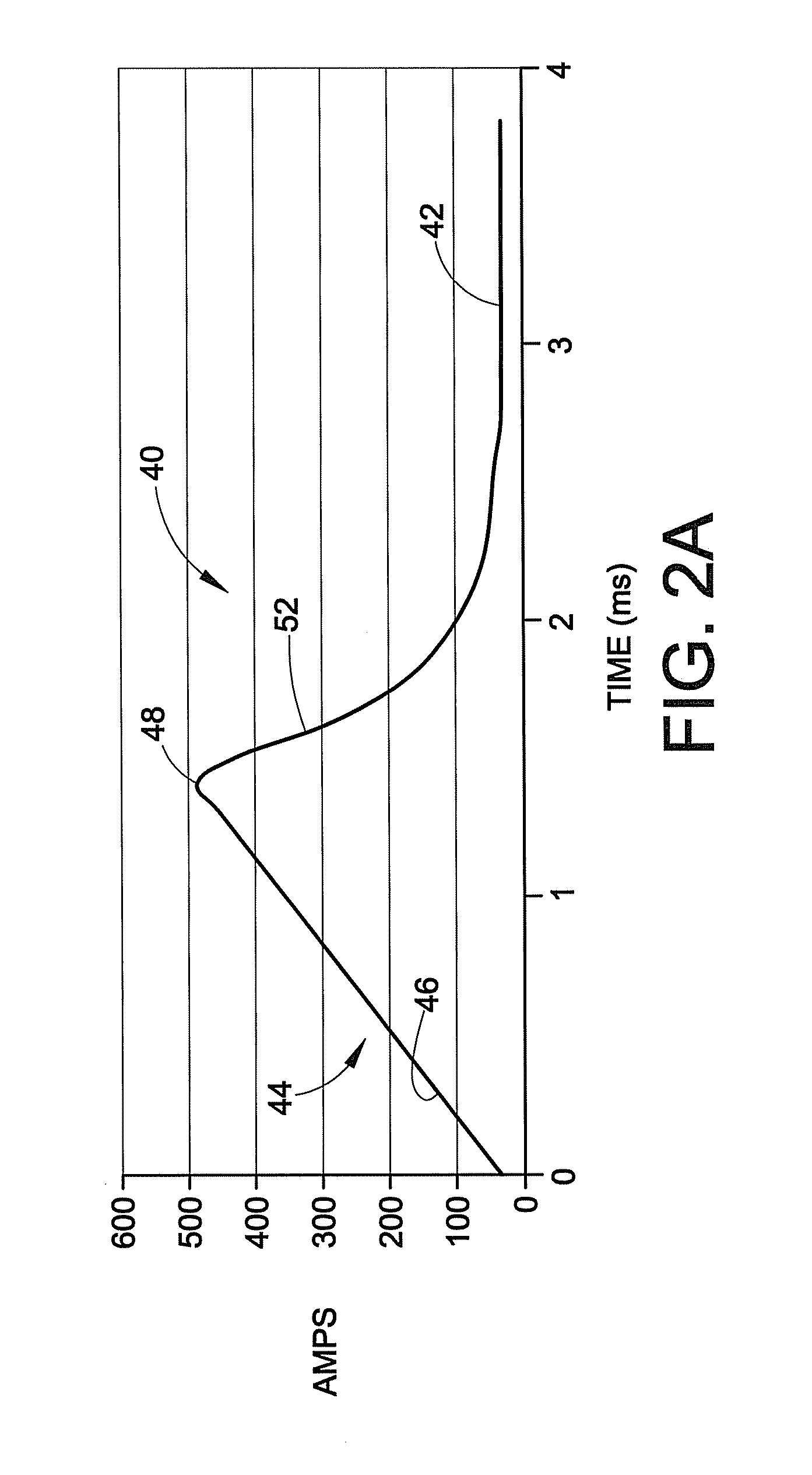
Method of arc welding root pass
a root pass and arc welding technology, applied in the direction of welding/cutting media/materials, welding apparatus, manufacturing tools, etc., can solve the problems of slow process and short arc welding, and achieve the effect of facilitating welding root pass joints
- Summary
- Abstract
- Description
- Claims
- Application Information
AI Technical Summary
Benefits of technology
Problems solved by technology
Method used
Image

Examples
example 1
Plate Material: A36 plate
Thickness: ¼ inch
Joint: 60 degree included angle
Land=0
Gap=0
No backer
Electrode 0.045 inch (1.2 mm) Super Arc™ L-56 Vertical orientation
Polarity: Positive pulse
Voltage: 21 Volts
Shielding Gas: 90% Argon 10% CO2
Wire Feed Speed: 300 inches / minute (7.62 meter / minute)
Power Source: POWER WAVE® 455M
Current: 180-200 amps
Stick out distance: ½ inch (12.7 mm)
Travel speed: 11-15 inches / minute
Torch angle: 15 degree Push
No Oscillation
example 2
Pipe Joint Material: X65 pipe (24 inch pipe)
Thickness: ½″
Joint: 60 degree included angle
Land=1.6 mm
Gap=1.6 mm
No backer
Electrode 0.052 inch Super Arc™ L-56
Polarity: Positive pulse
Voltage: 21.5 Volts
Shielding Gas: 85% Argon 15% CO2
Wire Feed Speed: 220 inches / minute
Power Source: POWER WAVE® 455M
Current: 202-235 amps
Stick out distance: 15 mm
Travel speed: 20 inches / minute
Torch angle: 0 to 10 degree Drag
Oscillation Frequency: 4 Hz / amplitude 1.5 mm / 0.04 L / R dwell
example 3
Thickness: ⅜ inch plate
No backer
Electrode 0.045 inch Super Arc™ L-59
Polarity: Positive pulse
Voltage: 21 Volts
Shielding Gas: 85% Argon 15% CO2
Wire Feed Speed: 460 inches / minute
Power Source: POWER WAVE® 455M
Current: 340 amps
Stick out distance: 1.5 inches
Travel speed: 40 inches / minute
Torch angle: 0 degree
Oscillation Frequency: Off
PUM
| Property | Measurement | Unit |
|---|---|---|
| thick | aaaaa | aaaaa |
| diameter | aaaaa | aaaaa |
| frequency | aaaaa | aaaaa |
Abstract
Description
Claims
Application Information