

Arc welding system, single arc welding system, and tandem arc welding system
- Summary
- Abstract
- Description
- Claims
- Application Information
AI Technical Summary
Benefits of technology
Problems solved by technology
Method used
Image

Examples
first embodiment
[Configuration of Arc Welding System: Single Arc Welding]
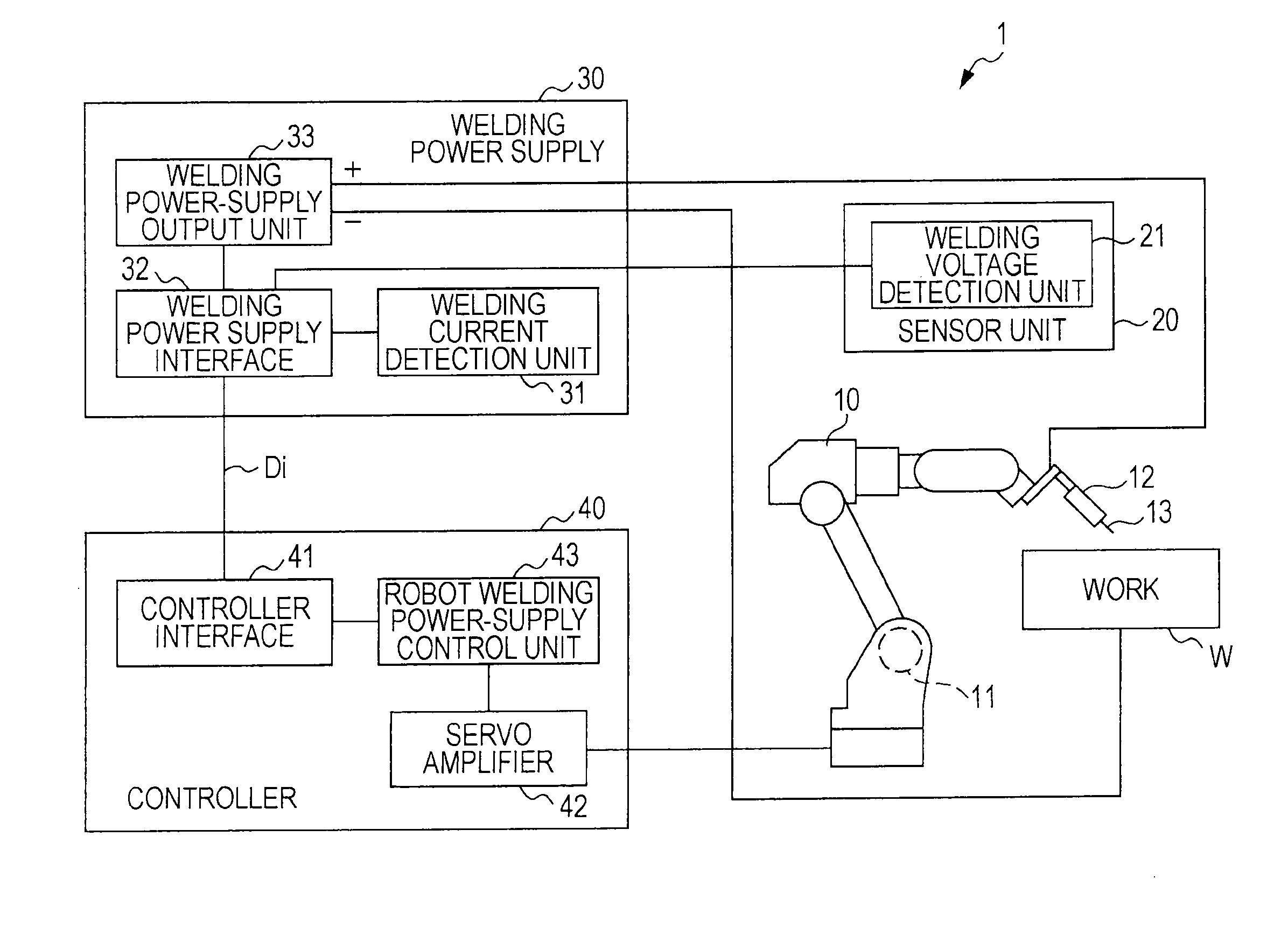
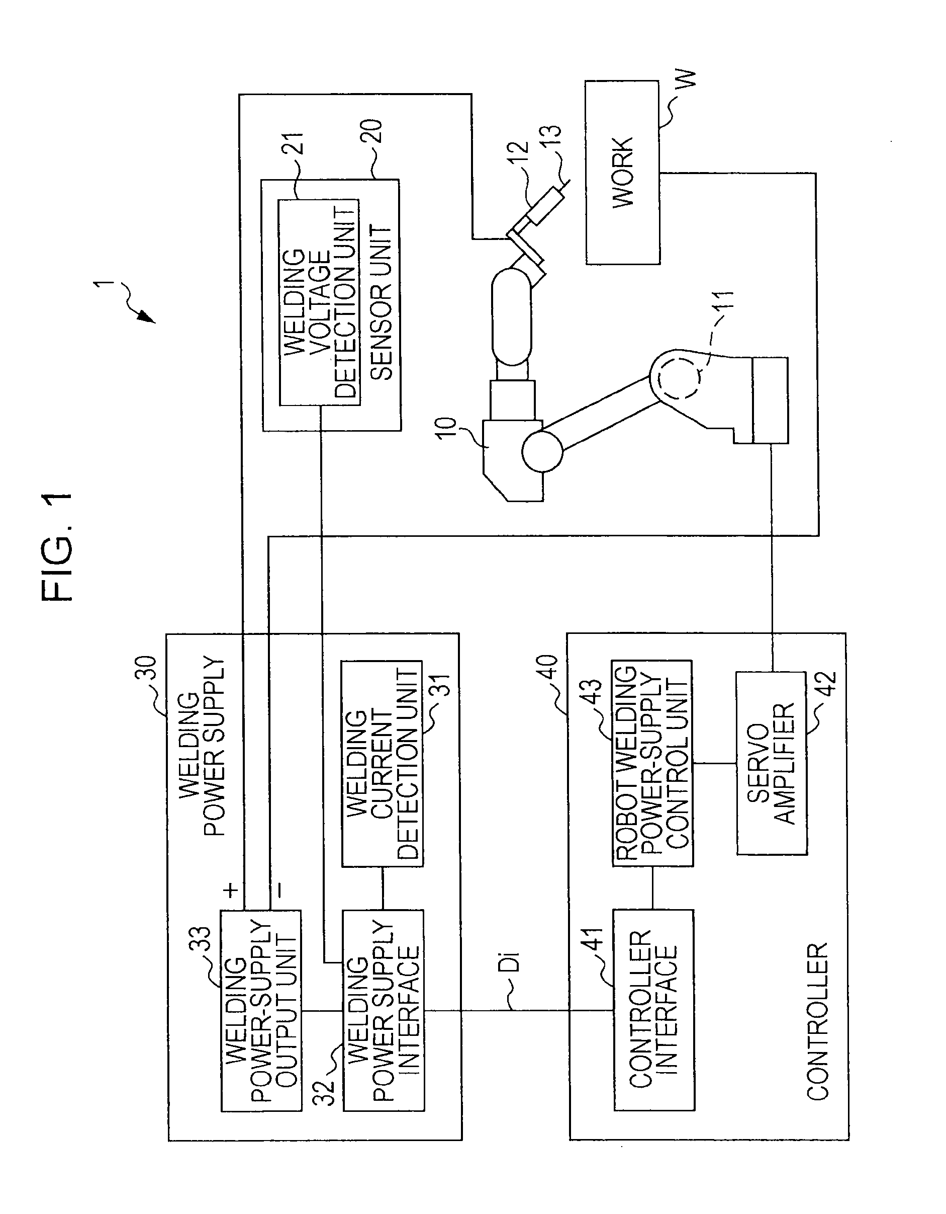
[0038]The configuration of an arc welding system according to a first embodiment of the present invention is described with reference to FIG. 1. As illustrated in FIG. 1, the arc welding system 1 is to carry out single arc welding, and it includes a welding robot 10, a sensor unit 20, a welding power supply 30, and a controller 40.
[0039]The welding robot 10 is an arc welding robot such as a 6-axis vertical articulated robot. When a motor drive signal is input to the welding robot 10 from a later-described servo amplifier 42, a built-in servo motor 11 is driven and the welding robot 10 is moved to be able to take a desired posture. The desired arc welding operation can be performed by mounting a welding torch 12 to an arm fore end of the welding robot 10, and by feeding a welding wire 13 to the welding torch 12 by a welding-wire feed motor (not shown). Be it noted that, for simplicity of explanation, only one servo motor 11 is ...
second embodiment
[Configuration of Arc Welding System: Tandem Arc Welding]
[0096]The configuration of an arc welding system (tandem arc welding system) 1A according to a second embodiment of the present invention is described with reference to FIG. 5. As illustrated in FIG. 5, the arc welding system 1A is to carry out tandem arc welding, and it includes a welding robot 10A, a sensor unit 20A, a sensor unit 20B, a first welding power supply 30A, a second welding power supply 30B, and a controller 40A.
[0097]The welding robot 10A includes a first welding torch 12A and a second welding torch 12B both mounted to an arm fore end thereof. The first welding torch 12A and the second welding torch 12B are each similar to the welding torch 12 in FIG. 1, and hence description of the welding torches 12A and 12B are omitted.
[0098]The sensor unit 20A includes a welding voltage detection unit 21A. The welding voltage detection unit 21A detects a welding voltage that is applied to a first welding wire 13A by a weldin...
example 1
[0154]EXAMPLES of the arc welding system described above in the second embodiment will be described below.
(Priority)
[0155]Frame priority will be described below as EXAMPLE 1 with reference to FIG. 7 when the CAN is employed as communication means. Be it noted that, in FIG. 7, other means in an arc welding system 1C according to the present invention than the first welding power supply 30A, the second welding power supply 30B, and the controller 40A are omitted.
[0156]In the arc welding system 1C of FIG. 7, tandem arc welding is carried out by outputting powers from a pair of two power supplies to one welding wire (one pole) in parallel and by employing two pairs of power supplies for two poles. More specifically, in the arc welding system 1C, the first welding power supply 30A is constituted by two power supplies (denoted by WP1(M) and WP1(S) hereinafter), and the second welding power supply 30B is constituted by two power supplies (denoted by WP2(M) and WP2(S) hereinafter).
[0157]Pri...
PUM
| Property | Measurement | Unit |
|---|---|---|
| Power | aaaaa | aaaaa |
| Electric potential / voltage | aaaaa | aaaaa |
Abstract
Description
Claims
Application Information