
Automotive Engine Cooling Pipe Apparatus and Method of Use

a technology for cooling pipes and engines, applied in mechanical equipment, machines/engines, lighting and heating apparatus, etc., can solve problems such as seal failure, seal damage, and installation that is extremely labor-intensiv

Active Publication Date: 2011-05-12
CHRISTENSEN HANS MARTIN
View PDF6 Cites 5 Cited by
  • Summary
  • Abstract
  • Description
  • Claims
  • Application Information

AI Technical Summary

Benefits of technology

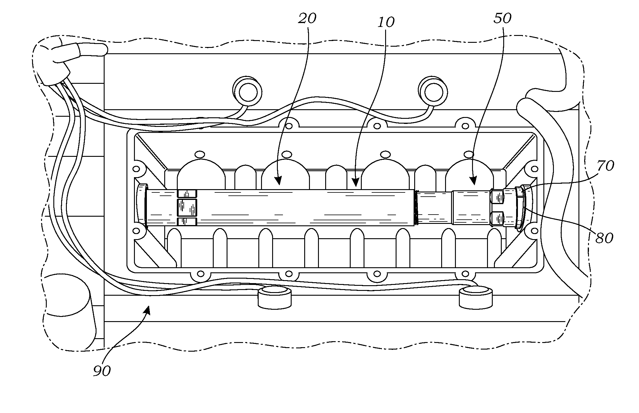
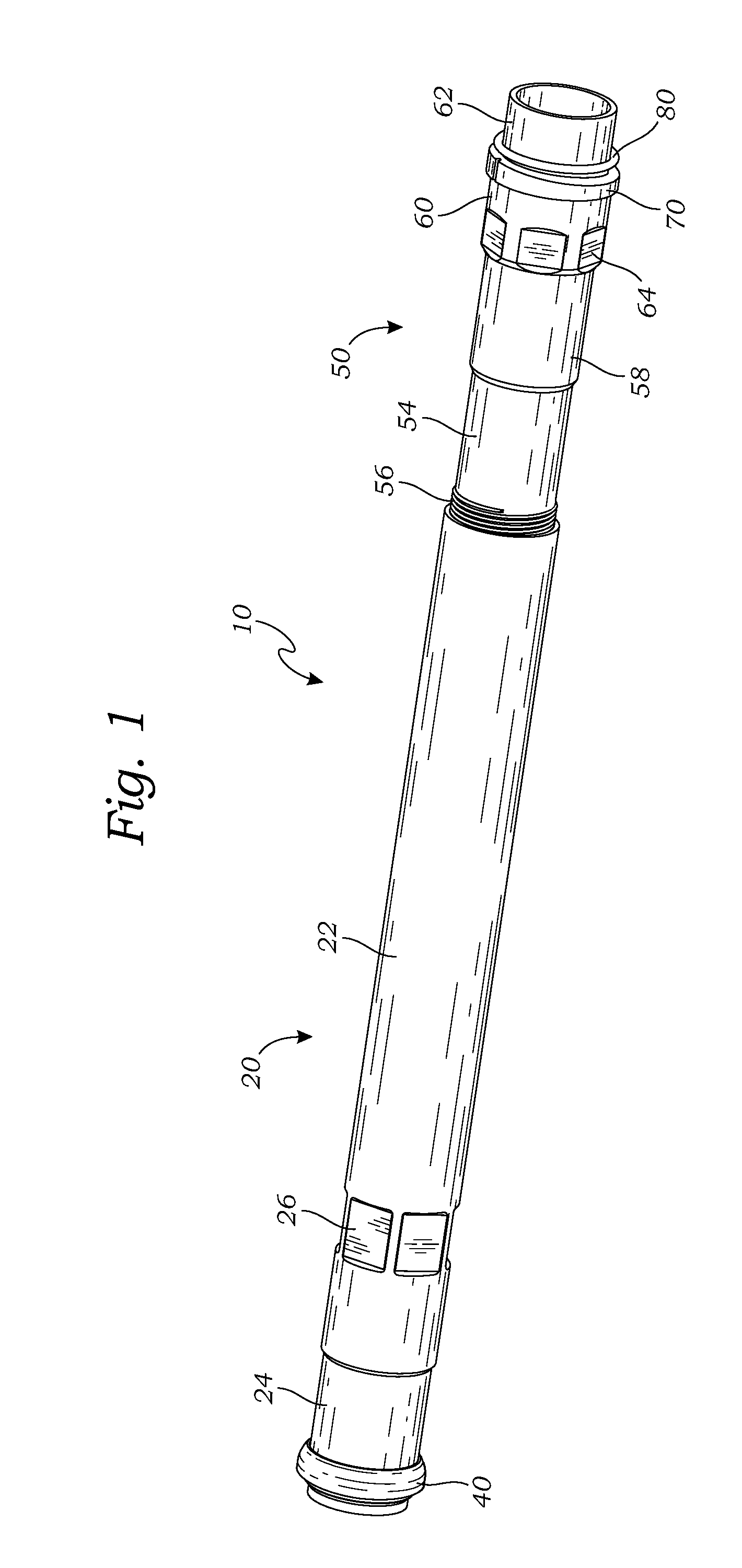
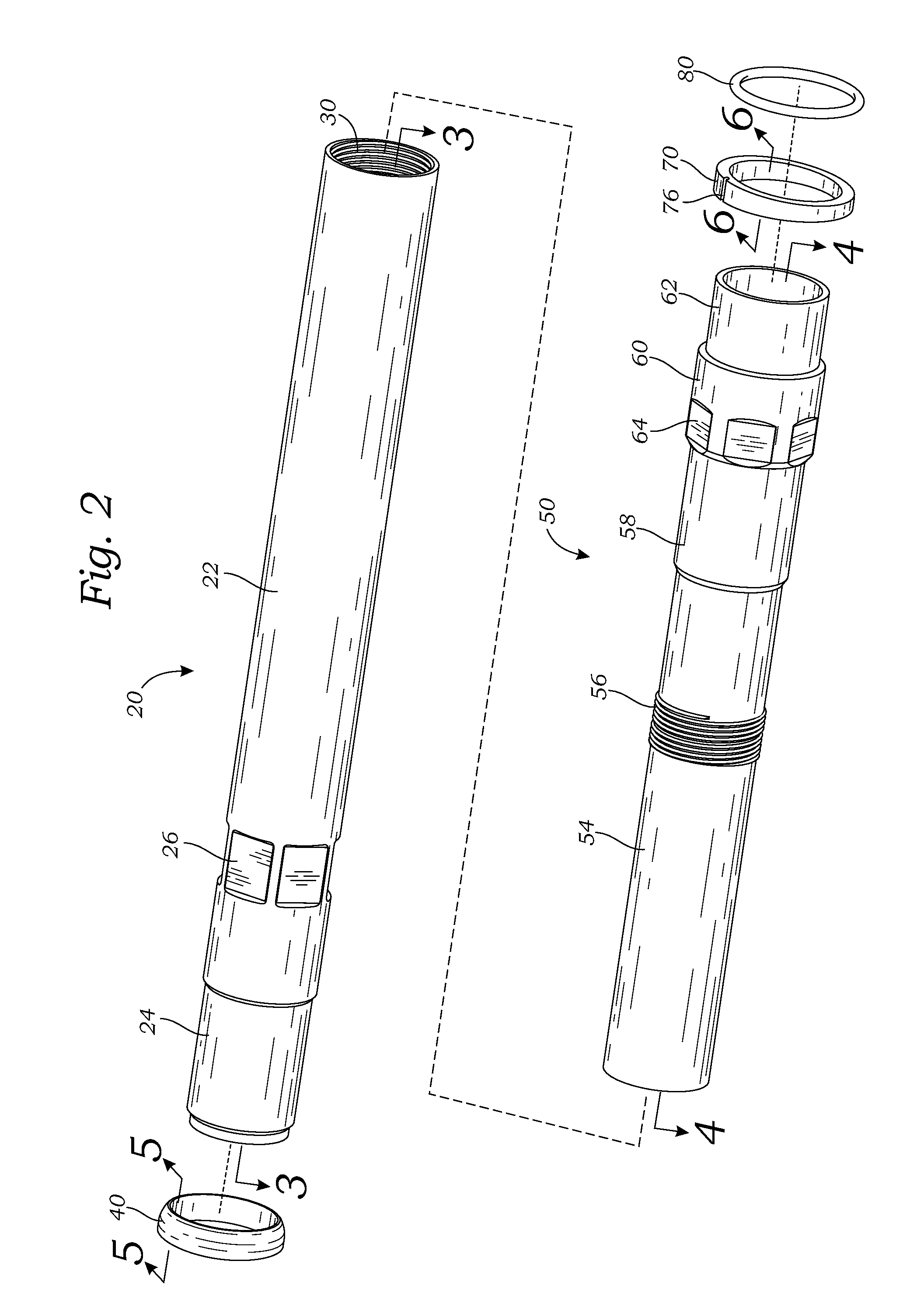
[0016]Generally, aspects of the present invention are directed to an automotive engine cooling pipe apparatus for fluid-conducting installation with an engine block of an engine comprising a front tube having a proximal portion configured for at least partially slidably and sealably engaging a front sealing ring seated within a front opening of the engine block, a rear tube telescopically received within the front tube and having a distal portion configured for at least partially slidably seating within a rear opening of the engine block, and a means for securing the relative positions of the telescoping front and rear tubes in a substantially expanded configuration of the apparatus, whereby expansion of the cooling pipe apparatus within the engine block seats the proximal and distal portions of the front and rear tubes within the respective front and rear openings of the engine block and so provides axial tension thereby stabilizing the installation of the cooling pipe apparatus within the engine block.
[0019]A further objective is to provide such an apparatus wherein a female thread portion is formed on the front tube and a male thread portion is formed on the rear tube and configured to threadably engage the female thread portion, whereby engagement of the female thread portion with the male thread portion and rotation of the front and rear tubes relative to one another causes selective contraction and expansion of the cooling pipe apparatus, the male and female thread portions thus cooperating with the crush ring and rear o-ring to provide axial tension and sliding and rotational resistance and thereby further stabilize the installation of the cooling pipe apparatus within the engine block.
[0020]A still further objective is to provide such an apparatus wherein the front tube is formed having a first enlarged bore that steps down to a second enlarged bore, the second enlarged bore is formed having two spaced-apart o-ring grooves, and two engagement o-rings are positioned within the o-ring grooves and configured to seal between the front tube and the rear tube when the front and rear tubes are telescopically assembled to form the cooling pipe apparatus, thereby preventing any fluid from passing between the second enlarged bore of the front tube and a rear outer wall of the rear tube when the apparatus is in use.

Problems solved by technology

Typically such cooling pipes must be installed axially or in a lengthwise direction from the front of the engine, making installation extremely labor-intensive, as compared to being able to somehow install such pipes laterally from above.
Over time, whether through failure to regularly replace the coolant or simply through normal “wear and tear,” the seal fails as its material just breaks down and corrosion underneath the seal around the pipe propagates and compromises the seal at that surface.
In order to repair this leak, the cooling pipe must be removed and replaced, requiring disassembly of much of the engine, including the intake manifold, water pump, valley pan, valve covers, timing covers, and timing assembly, the entire job then typically requiring on the order of 60-70 man-hours and so being quite expensive.
Accordingly, using the BMW cooling pipe or transfer tube to repair this coolant leak necessitates the time-consuming and expensive removal and reassembly of much of the front of the engine.
The prior art described above teaches an extensible lubricant-return tube for internal combustion engines, a linear adjustable telescopic nipple, a telescoping pipe coupling with improved pressure seal connection threads, a dual conduit drill stem member, and an extensible metallic tube structure, but does not teach an automotive engine cooling pipe apparatus for fluid-conducting installation with an engine block of an engine laterally or “from above” as facilitated by a telescoping, tube-in-tube construction of the apparatus.

Method used


Image

  • Automotive Engine Cooling Pipe Apparatus and Method of Use
  • Automotive Engine Cooling Pipe Apparatus and Method of Use
  • Automotive Engine Cooling Pipe Apparatus and Method of Use

Examples


Embodiment Construction

[0031]The above described drawing figures illustrate aspects of the invention in at least one of its exemplary embodiments, which are further defined in detail in the following description.

[0032]Generally, the automotive engine cooling pipe apparatus of the present invention addresses the above-described problem and others by essentially providing a telescoping or collapsible and expandable tube-in-tube cooling pipe construction that enables the pipe to be sufficiently shortened so as to be installed “from above” and then, once in position, lengthened to properly seat and seal at opposite ends within an engine block. As such, the telescoping cooling pipe or transfer tube of the present invention enables repair of a coolant leak in an engine employing such cooling pipes through replacement of the failed seal and the associated pipe by accessing the necessary engine block area without removal of the valve and timing covers and timing assembly, thereby providing tremendous labor saving...


PUM

PropertyMeasurementUnit
obtuse angleaaaaaaaaaa
lengthaaaaaaaaaa
angleaaaaaaaaaa

Abstract

An automotive engine cooling pipe apparatus for fluid-conducting installation with an engine block of an engine comprising a front tube having a proximal portion configured for at least partially slidably and sealably engaging a front sealing ring seated within a front opening of the engine block, a rear tube telescopically received within the front tube and having a distal portion configured for at least partially slidably seating within a rear opening of the engine block, and a means for securing the relative positions of the telescoping front and rear tubes in a substantially expanded configuration of the apparatus, whereby expansion of the cooling pipe apparatus within the engine block seats the proximal and distal portions of the front and rear tubes within the respective front and rear openings of the engine block and so provides axial tension thereby stabilizing the installation of the cooling pipe apparatus within the engine block.

Description

RELATED APPLICATIONS[0001]This application claims priority and is entitled to the filing date of U.S. Provisional application Ser. No. 61 / 409,068 filed Nov. 1, 2010, and entitled “Automotive Engine Cooling Pipe Apparatus and Method of Use.” The contents of the aforementioned application are incorporated by reference herein.INCORPORATION BY REFERENCE[0002]Applicant hereby incorporates herein by reference any and all U.S. patents and U.S. patent applications cited or referred to in this application.BACKGROUND OF THE INVENTION[0003]1. Field of the Invention[0004]Aspects of this invention relate generally to automotive parts, and more particularly to an improved automotive engine cooling pipe.[0005]2. Description of Related Art[0006]The subject of this patent application is an improved automotive engine cooling pipe particularly configured for installation in engines wherein such a cooling pipe is originally factory-installed. Typically such cooling pipes must be installed axially or in...

Claims


Application Information

Patent Timeline
Patent Type & Authority Applications(United States)
IPC IPC(8): F16L27/12B21K3/00
CPCF01P11/04Y10T29/49231F28F1/00F16L25/12
Inventor CHRISTENSEN, HANS MARTIN
Owner CHRISTENSEN HANS MARTIN
Learn More