Switched mode power converter and method of operating the same

a power converter and switch mode technology, applied in pulse generators, pulse techniques, instruments, etc., can solve the problems of relatively complex circuits, adds to the complexity and cost of generators, etc., and achieves the effect of smoothing capacitors

Inactive Publication Date: 2011-05-12
NXP BV
View PDF8 Cites 50 Cited by
  • Summary
  • Abstract
  • Description
  • Claims
  • Application Information

AI Technical Summary

Benefits of technology

[0020]Preferably the switched mode power converter comprises a smoothing capacitor. Since the inductor currents in such a switched mode power conve...

Problems solved by technology

Unfortunately, a current converter operated in CCM requires some time for the current to ramp up again; thus the current generator needs to turn on prior to the time when the bypass switch stops conducting.
Although it is ...

Method used


Image

  • Switched mode power converter and method of operating the same
  • Switched mode power converter and method of operating the same
  • Switched mode power converter and method of operating the same

Examples


Embodiment Construction

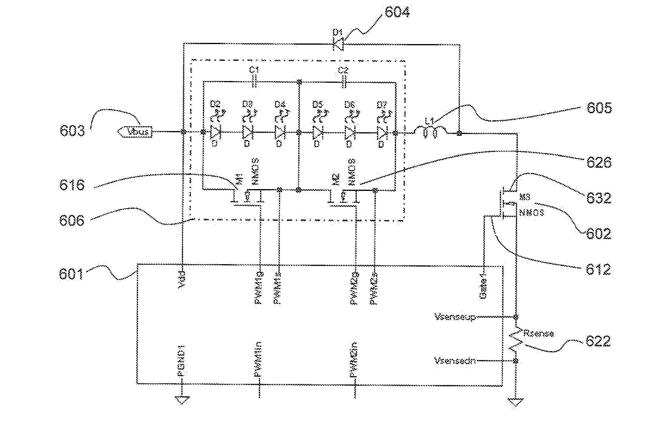
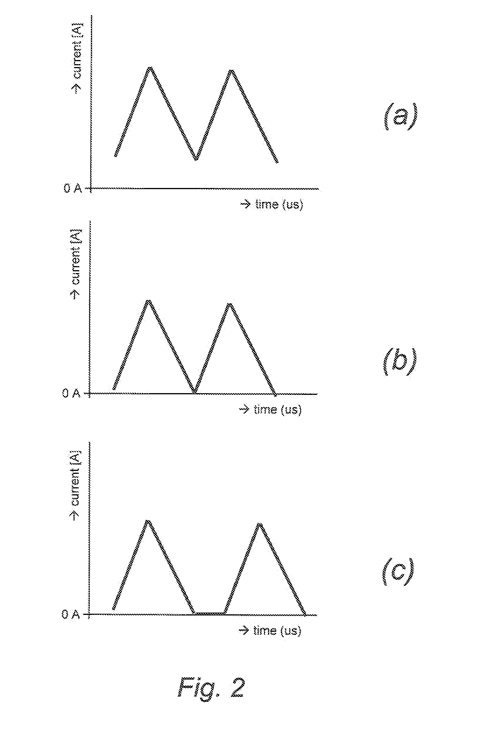
[0033]In a method according to one aspect of the present invention, boundary conduction mode (BCM) is used to control the power converter. In this conduction mode the coil current reverts to zero during every conversion cycle. Thus this conduction mode may be characterised by the quasi continuous variation of the inductor current between zero and a maximum level. In order to provide a near constant output current, the maximum level of current through the inductor is thus twice the output current. This represents a large output ripple; thus a smoothing or filter capacitor on the output is generally required. On the other hand, soft switching is enabled since the switching may be performed at zero current or zero voltage. Consequently, for a non-synchronous implementation of the switch-mode power converter the freewheel diode turns off at zero current allowing for a cheap silicon diode instead of an expensive Schottky diode. Moreover, because the boundary conduction mode supports zero...


PUM


Abstract

A switched mode power converter is disclosed, together with a method for operating the same. The power converter is adapted to be operable in the boundary conduction mode, and operation is interruptible in the absence of any load requirement.

Description

FIELD OF THE INVENTION[0001]This invention relates to switched mode power converters and a method of operating the same.BACKGROUND OF THE INVENTION[0002]The current to drive light emitting diodes (LED) for lighting and other applications is commonly provided by a switched mode power supply or other switched mode power converter. Moreover, a single switched mode power converter may be able to provide the current required for multiple LEDs or LED strings. In some applications it is desirable to be able to separately control or dim such individual LEDs or LED strings. It is well known to provide bypass switches in order to provide this control function. In circumstances when all the bypass switches connected to a switched mode power converter operating as an LED current generator are conducting, such that all the LEDs are off, it is feasible to also turn off the current generator in order to save power.[0003]The power savings that can be obtained by switching off a current generator fo...

Claims


Application Information

Patent Timeline
IPC IPC(8): H05B33/08H03K3/011H05B44/00
CPCH05B33/0818H05B33/0815Y02B20/346H05B33/083H05B45/48Y02B20/30H05B45/375
Inventor HOOGZAAD, GIANDEURENBERG, PETER HUBERTUS FRANCISCUS
Owner NXP BV
Why Eureka
Try Eureka