Rotation angle sensor

a technology of rotation angle and sensor, which is applied in the direction of measuring devices, instruments, dynamo-electric machines, etc., can solve the problems of increasing the size of the motor, affecting the detection output, and the resolver is liable to be influenced by the disturbance of electromagnetic noise of the motor, so as to achieve small difference in generated induced voltage and poor s/n ratio

Inactive Publication Date: 2011-05-12
AISAN IND CO LTD
View PDF18 Cites 38 Cited by
  • Summary
  • Abstract
  • Description
  • Claims
  • Application Information

AI Technical Summary

Benefits of technology

[0022]The synchronous detector angle sensor of the invention provides the following operations and effects. With the above configuration (1), in the sine wave coil and the cosine wave coil facing the magnetic part or the cutout of the resolver rotor, respective predetermined detection currents flow. In other words, when the excitation signal (the sine wave signal) is input to the excitation coil, the excitation coil generates a predetermined amount of magnetic flux in a positive direction (representing a direction of the magnetic flux generated by the excitation coil). This magnetic flux passes through the magnetic part of the resolver rotor to form a magnetic circuit. Thus, the magnetic flux is frequently generated. Detection voltage which is an induced voltage generated by the generated magnetic flux becomes large.
[0023]On the other hand, the detection current hardly flows in the parts of the sine wave coil and the cosine wave coil, the parts facing the nonmagnetic conductive part of the resolver rotor. The reason

Problems solved by technology

Otherwise, outputs of the circumferentially arranged coils cancel each other and thus appropriate detection output could not be obtained.
When the resolver is used for the motor shaft for driving the robot arm, there is a problem with an increased size of the motor.
Thus, this

Method used


Image

  • Rotation angle sensor
  • Rotation angle sensor
  • Rotation angle sensor

Examples


second embodiment

[0164]A second embodiment of an amplitude resolver according to the present invention will be explained below referring to accompanying drawings. The second embodiment is identical to the first embodiment excepting only the shape of a resolver rotor 102. Identical parts are given the same reference signs as those in the first embodiment and their explanations are not repeated herein.

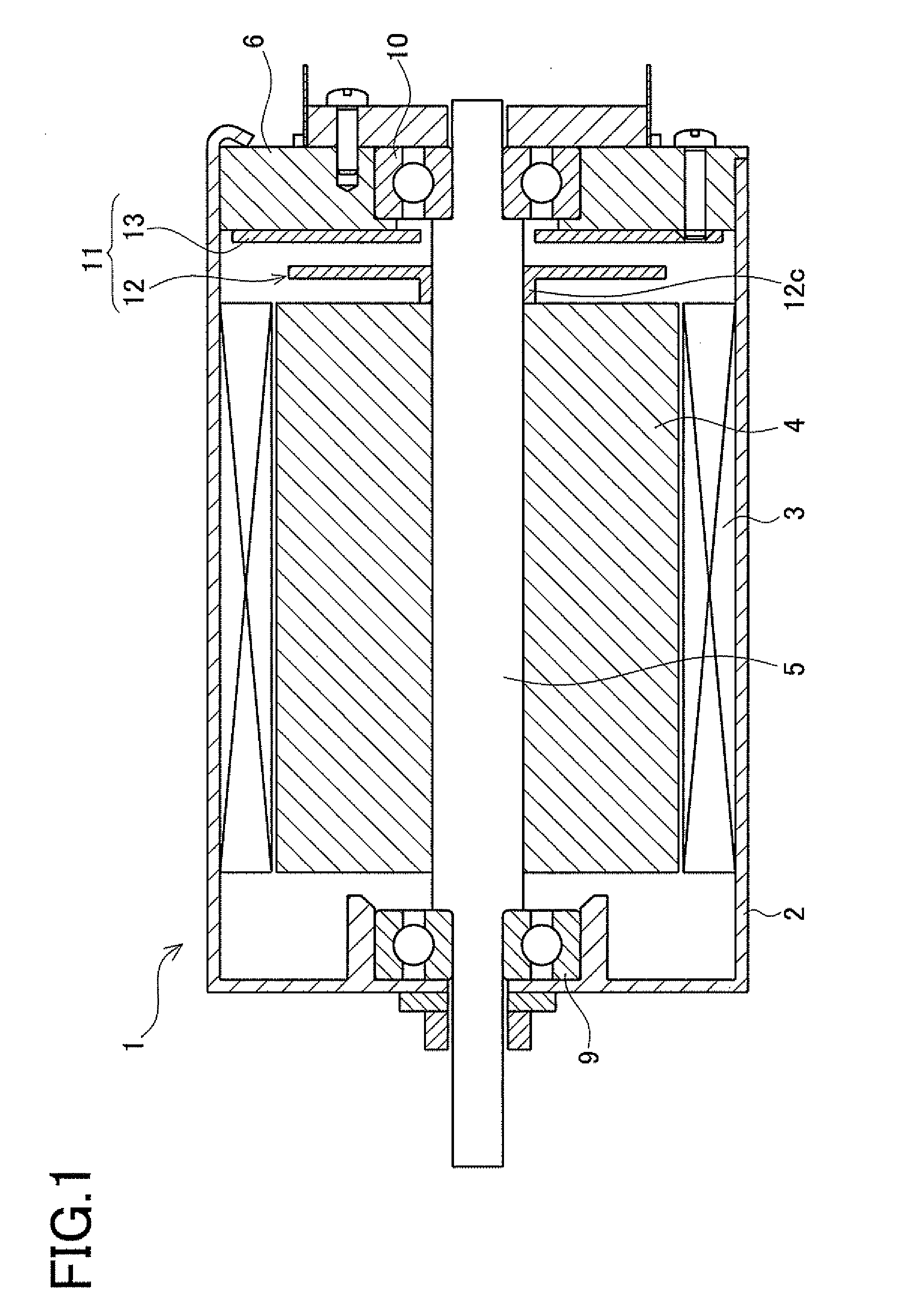
[0165]FIG. 17 is a sectional view of one end part of a resolver-mounted motor 1 (hereinafter, simply referred to as a “motor”). FIG. 18 is an enlarged sectional view showing a part enclosed by a dashed line X1 in FIG. 17. FIG. 19 is an enlarged sectional view showing a part in FIG. 18. As shown in FIG. 17, the motor 1 includes a motor case 2, a motor stator 3 and a motor rotor 4 placed in the motor case 2, and a motor shaft 5 integrally provided in the center of the rotor 4. One end of the shaft 5 slightly protrudes out of the case 2. The case 2 includes a main case body 6A and an end plate 7 fixed to cl...

third embodiment

[0216]A third embodiment of a resolver embodying the present invention will be explained below with reference to accompanying drawings.

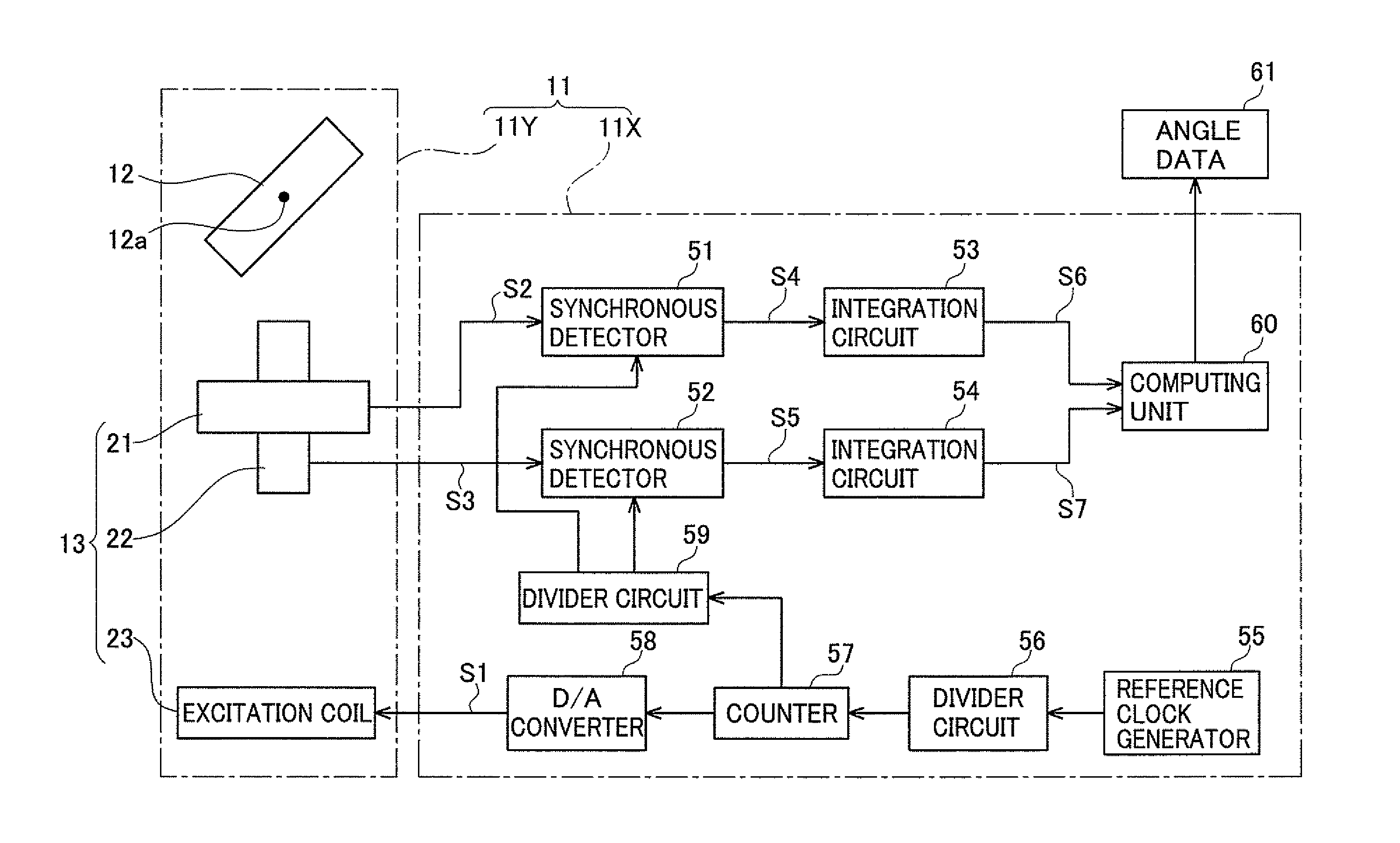
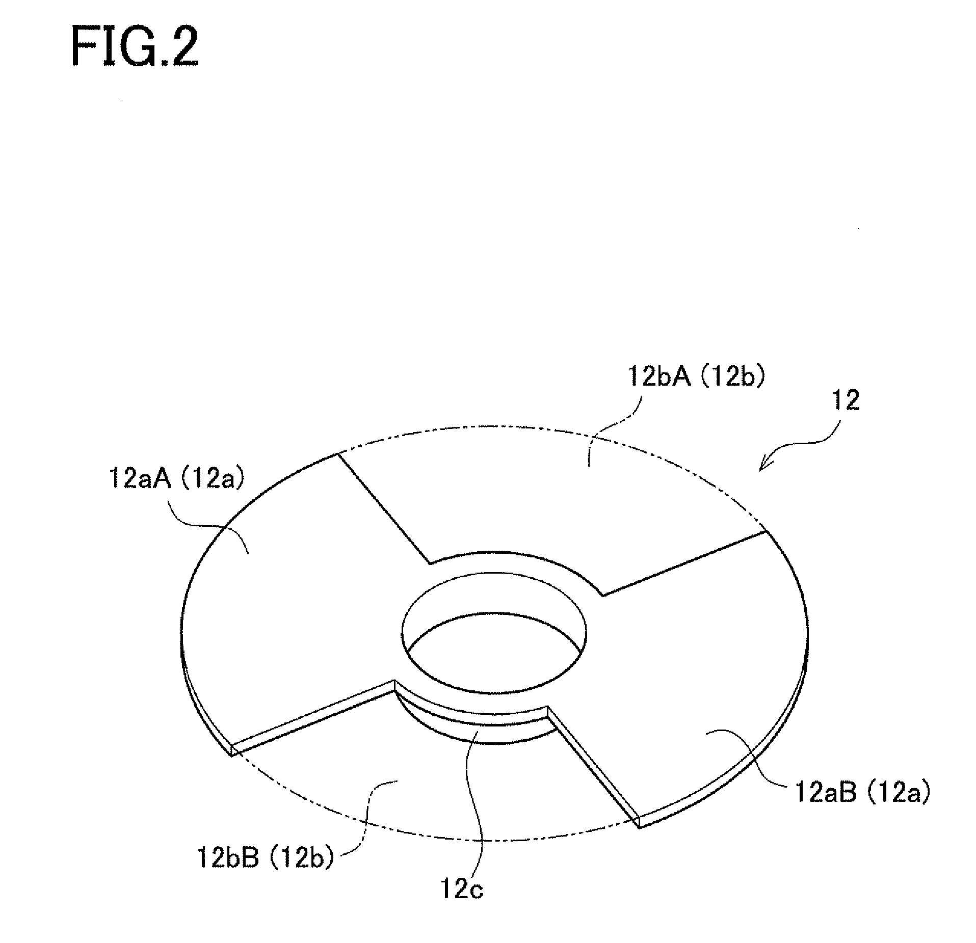
[0217]In a resolver 11 in the third embodiment, a mounting structure thereof is identical to that in FIG. 1 in the first embodiment and its details are not repeated herein. Further, a structure of a resolver rotor 12 is identical to that in FIG. 2 in the first embodiment and its details are not repeated herein. A circuit section 11X is also identical to that in FIG. 3 in the first embodiment and its details are not repeated herein.

[0218]The operations of an excitation coil 123, the resolver rotor 12, a sine wave coil 121, and a cosine wave coil 122 will be explained below. Graphs (a) to (d) in FIG. 29 show the operations and characteristics of the resolver. In FIG. 29, (a) shows a positional relationship between a resolver stator 113 (a stator base flat plate 130, the excitation coil 123, the sine wave coil 121, and the cosine wave coil 122) and the ...

fourth embodiment

[0262]A fourth embodiment of a rotation angle sensor according to the present invention will be explained in detail below referring to accompanying drawings. The following explanation is made so that identical components to those in the third embodiment are given the same reference signs and with a focus on differences from the third embodiment.

[0263]The fourth embodiment differs from the third embodiment in the structure of the resolver stator 113 and in particular in the structures of the excitation coils 124 and 125 and the detection coils 132 and 134. FIG. 38 is an exploded perspective view of the resolver stator 113. FIG. 39 is an exploded, enlarged perspective view of part of the components shown in FIG. 38. FIG. 40 is a perspective view of an exploded, enlarged perspective view of part of the components in FIG. 38.

[0264]As shown in FIG. 38, the resolver stator 113 includes a base flat plate 130, an insulating layer 131, a first excitation coil 124, an insulating layer 136, a ...


PUM


Abstract

A rotation angle sensor comprises: a resolver stator including an excitation coil for receiving an excitation signal and a detection coil (a sine wave coil and a cosine wave coil) for outputting a detection signal; and a resolver rotor rotatably placed to face the stator. The resolver stator is formed on a stator flat plate. The resolver rotor is made of a flat-shaped rotor flat plate. The stator flat plate and the rotor flat plate are placed in parallel to face each other. The rotor flat plate is formed with a cutout.

Description

CROSS-REFERENCE TO RELATED APPLICATIONS[0001]This application is based upon and claims the benefit of priority from each of the prior Japanese Patent Applications No. 2009-256560 filed on Nov. 9, 2009, No. 2009-295819 filed on Dec. 25, 2009, and No. 2010-067730 filed on Mar. 24, 2010, the entire contents of which are incorporated herein by reference.TECHNICAL FIELD[0002]The present invention relates to a rotation angle sensor including a stator provided with an excitation coil which receives an excitation signal and a detection coil which outputs a detection signal and a rotor which is placed facing the stator and rotates.BACKGROUND ART[0003]Heretofore, a high-power compact brushless motor has been used in a robot arm and others. To control the compact brushless motor of the robot, the rotational position of an output shaft has to be detected accurately. This is because the rotation angle of a rotor has to be ascertained precisely for controlling switching of energization to each co...

Claims


Application Information

Patent Timeline
IPC IPC(8): G01B7/30
CPCH02K3/26H02K29/12H02K24/00
Inventor SUZUKI, SHINYANAKAMURA, TAKEHIDEINOUE, TOMOAKIKANEMITSU, RYOJIRO
Owner AISAN IND CO LTD
Why Eureka
Try Eureka